CWDM for the Subsea Market


-
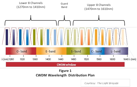
 Figure 1
-
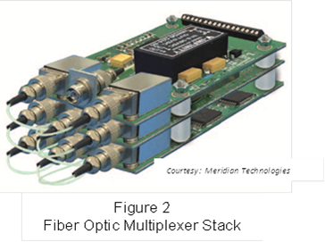 Figure 2
-
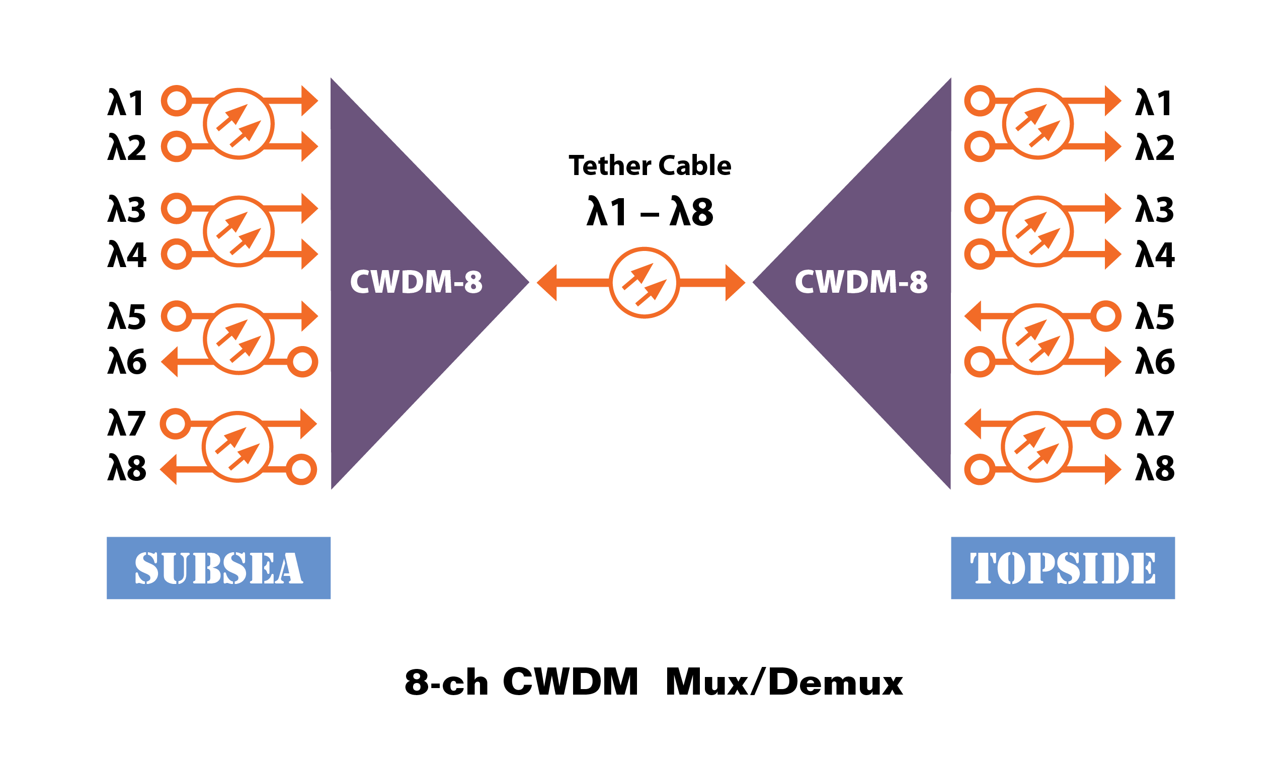
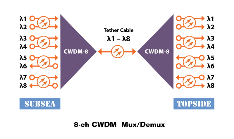 Figure 3

Originally developed for the Metro Telecom market, CWDM (Coarse Wavelength Division Multiplexing) technology has become ubiquitous in all telecom markets as well as the subsea market.
CWDM is a cost-effective and technology-efficient way to multiplex a number of signals on one fiber. There are a number of wavelength multiplexing techniques that can be utilized, depending on the number of wavelengths. Standard WDM (Wavelength Division Multiplexing) utilizes either two, three or in some instances four wavelengths using standard lasers. CWDM technology can multiplex up to 18 individual wavelengths onto a single fiber. DWDM (Dense Wavelength Division Multiplexing) can typically multiplex 40 or 80 wavelengths on a single fiber. More elaborate DWDM techniques allow even higher density wavelength multiplexing. The most common method for wavelength multiplexing in the subsea market is CWDM where lower cost lasers and laser drivers can be used while maintaining the ability to multiplex a wide variety and quantity of unidirectional and bidirectional signals.
While CWDM technology is available for both single-mode and multimode systems, single-mode is the most common type as it offers increased multiplexing and distance capabilities. Most CWDM systems area available in increments of 4 wavelengths or channels (from 4 to 16 wavelengths). Figure 1 illustrates the CWDM wavelength plan. The first or lowest wavelength is 1270nm while the longest wavelength is 1610nm in increments of 20nm. While some systems are available with 18 wavelength, most utilize up to 16 wavelengths leaving the middle two (1430 and 1450nm) as a guard band when combining the lower 8 with the upper 8 wavelengths.
There are three unique elements in a CWDM system – Wavelength- specific laser, CWDM multiplexer and CWDM demultiplexer.
Lasers – Lasers used in CWDM systems are the type known as DFB (Distributed FeedBack) lasers. The main characteristic of these lasers that is important in CWDM systems is the narrow spectral width, or wavelength spread of the laser’s light. The more common laser used in many fiber systems is the FP or Fabry-Perot. These lasers have a spectral width on the order of 3-6 nm while the DFB lasers have a spectral width of 0.1 nm or less, making them perfect for use in CWDM and DWDM (Dense Wavelength Division Multiplex) systems. As the curve in Figure 1 illustrates, these DFB lasers for CWDM systems range in wavelengths from 1270nm to 1610nm, in increments of 20nm. One of the advantages of CWDM systems over DWDM is that the CWDM lasers do not require temperature compensation in order to keep the wavelength from drifting. The wavelength variation of these DFB lasers as a function of temperature is on the order of 0.1nm/DegC. The passband of the CWDM multiplexer and demultiplexer is on the order of 10nm to 13nm, depending on manufacturer and design. In addition, the absolute wavelength of the lasers can vary by a couple nanometers. As such, the operating temperature range of the lasers and transmission equipment is approximately 70 to 100 degC, typically around 80 degC. Taking into account the various component tolerances and the laser’s temperature drift, this results in an operating temperature range of approximately -10 oC to +70 oC – well within the range of subsea systems. DWDM systems, on the other hand, require elaborate wavelength stabilization circuits to keep the laser’s wavelength from drifting at all as a function of temperature and performance variations.
CWDM Multiplexer/Demultiplexer – CWDM mux/demux devices are typically available in 4 or 8 channel increments.
The common bands are as follows:
Band 1 (4-channel) ............................. 1510 through 1570nm
Band 2 (8-channel) .............................. 1470 through 1610nm
Band 3 (12-channel) ............................ 1310 through 1370nm
Band 4 (16-channel) ............................ 1270 through 1610nm
All of these wavelength channels are separated in increments of 20nm. Note that the individual wavelengths will be listed as either even or odd wavelengths such as 1530nm or 1531nm. The original CWDM wavelength plan had the lasers identified with even wavelengths. In 2003 the ITU (International Telecommunications Union) revised the specification by 1nm so that the wavelength overall CWDM plan goes from 1271 to 1611nm instead of 1270 to 1610nm. CWDM and mux/demux manufacturers may specify the wavelengths in either format. They are interchangeable.
Bidirectional Transmission – CWDM technology offers an excellent platform for bidirectional transmission of a number of signals over one single-mode fiber. In order to facilitate bidirectional transmission of signals (e.g., Ethernet, data, etc.), two wavelengths must be assigned – one for each direction of the signal. Using TDM (Time Division Multiplexing) each wavelength can support a number of signals. For example, using two wavelengths, you can transmit multiple videos as well as one direction of data or Ethernet while the second wavelength supports the return direction of the data. Since fiber optics is signal agnostic, each wavelength can support any type of signal from the simplest of a contact closure or TTL to the more complex, high bandwidth HDSDI and GigE signals. A typical 8-ch CWDM mux/demux can support a significant amount of both unidirectional and bidirectional signals. These signals generally include the following: Analog video, HDSDI video, Ethernet (either 10/100 or GigE), data, and TTL. Depending on the ROV type and the specific mission, other signals such as audio, USB and contacts might be transmitted.
System architecture – The optical transmission devices are somewhat unique in CWDM and DWDM systems. From the transmit standpoint, each of the CWDM lasers has a unique wavelength and is connected to its complementary wavelength port on the CWDM multiplexer. The optical receiver, on the other hand, uses a broadband optical detector that will respond to all wavelengths over the entire CWDM wavelength plan (1270 through 1610nm). The wavelength separation is accomplished in the CWDM demultiplexer. Therefore, the receivers do not have any wavelength specific devices that would mate to unique wavelengths on the CWDM demultiplexer. For example, if a 4-ch CWDM system utilizes 4 HDSDI signals, each operating on a separate wavelength, there would be 4 unique parts numbers for these transmitters (one for each of the 1510 through 1570nm wavelengths). However, since the wavelength demultiplexing or separation is done in the demultiplexer, all four of the HDSDI receivers would have the same part number and would be interchangeable. In general, the CWDM multiplexer and demultiplexer can be the same part #. While the specifications are slightly different for the mux and demux devices, since most of the subsea applications will utilize bidirectional signal transmission, the CWDM mux device will work well for both the subsea and topside equipment.
The CWDM mux/demux modules are small and can be housed in between any of these boards. Small 900μm fiber patch cords from each of the fiber Tx/Rx cards are connected to the internal CWDM mux module. The output of the mux is a single optical port which is then connected to the tether for transmission topside. The fiber inside the tether then connects to the topside receiver card and connects to the input of the CWDM demultiplexer. This module then separates each of the wavelengths from the subsea transmission equipment and adds any wavelengths from the topside equipment that are to be transmitted to the subsea unit. Note that the typical optical connector interface will typically have a UPC (Ultra Physical Contact) end finish so that optical reflections are kept to a minimum. It is important that this UPC finish be on both ferrules of a mated connector. While it may be common practice to use the typical “grind and polish” technique for ship-board terminations, it is not recommended as connector losses and optical reflections will be higher than expected and there exists the possibility for damaging the connector ferrules when mating ferrules with different end polishes. This will be discussed in more detail in a subsequent article on connector terminations, cleaning and inspection.
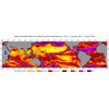
Wavelength Testing – Since the power from all the transmitted wavelengths are present on the common tether fiber simultaneously it requires a special power meter to identify the presence of each wavelength on the tether and its optical power level. Traditional power meters have a wide, nonselective wavelength detector. Since the tether fiber has all the wavelengths this power meter will read the sum of all of these wavelengths and will not identify the power associated with each wavelength. In order to utilize a standard power meter, an optical CWDM demultiplexer must be used to separate each of the wavelengths before being connected to the power meter. While this will work, it will introduce an additional part (demultiplexer) which will have its own optical loss, thus compromising the test results. As shown in the above fiber multiplexer stack, gaining access to the output of each demux port may be difficult for use with a standard power meter.
Figure 3 illustrates a typical bidirectional CWDM optical interconnect application. Wavelengths 1-5 and 7 are used to transmit information topside while wavelengths 6 and 8 receive data from the topside location. These ‘return’ signals may be Ethernet data, contact closures, etc. Each fiber at the input/output of the optical mux carries its own unique wavelength. Therefore a standard power meter will work to measure the wavelength’s optical power on its associated fiber. However, the common port of the mux/demux contains all of the wavelengths on the one fiber. This is where the CWDM power meter becomes useful.
CWDM power meters will demultiplex each of the individual wavelengths present on the tether’s fibers and report their associated power either in a graphical or tabular format. These meters have various features which allow individual wavelength’s power to be displayed or displayed as a group and output for further processing. Considering how ubiquitous CWDM is in the ROV market, it would seem prudent to have one of these CWDM power meters as part of the technician’s equipment list.
CWDM provides a significant amount of signal transmission versatility. The combination of TDM and CWDM gives the system an almost unlimited ability to view, monitor, and control all aspects of an ROV’s functions over significant distances with zero latency. As this article highlights, CWDM is a proven technology with exceptional capabilities and expansion potential.
For more information email the author at [email protected].
(As published in the March 2016 edition of Marine Technology Reporter: http://www.marinetechnologynews.com/magazine)