Optimizing Cathodic Protection Survey Using Non-contact Sensors


-
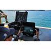
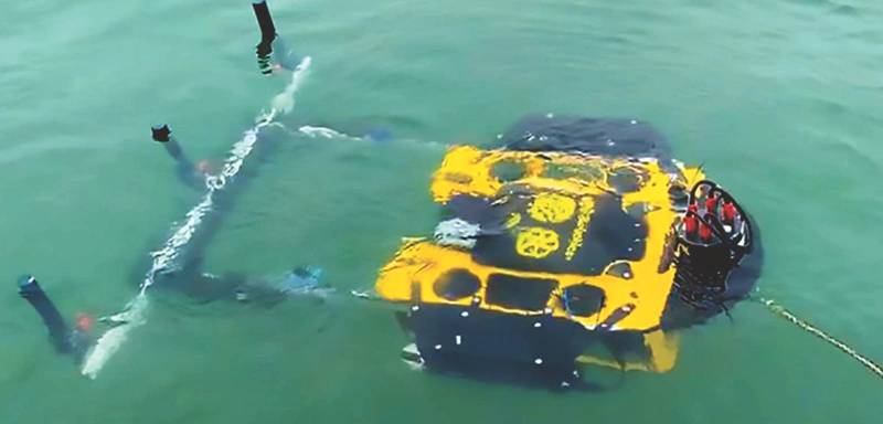 Image courtesy FORCE Technology
-
 About the Author: Svenn Magen Wigen is a Cathodic Protection and corrosion control expert having worked across engineering, design, modelling, project management, inspection, sales, marketing and management in the sector since 2001.


The principle behind sacrificial anodes, which are used to safeguard underwater pipelines and structures from corrosion, is relatively straightforward. Made of alloys like aluminum, Zinc and is some cases Magnesium, the anodes are more reactive in the electrochemical process than the steel used in pipelines and other subsea structures. When connected to a structure, the anodes willingly 'sacrifice' themselves by corroding first, effectively redirecting the corrosion away from the vital structures.
The methodology, known as Cathodic Protection (CP), is used on all underwater structures that consist of two or more touching metals, and therefore act like a battery in seawater, creating a current that causes consumption of the anode material. The practice significantly extends the lifespan of underwater structures, reducing the need for frequent repairs and replacements, which also aligns well with sustainable operational practices in the offshore industry. However, in order to protect underwater assets effectively, the condition of CP anodes must be regularly surveyed to determine when replacements are required.
Survey Methods
CP survey is part of a larger underwater integrity management strategy, normally consisting;
- Identification of threats,
- Assessment of risk associated with the identified threats,
- Inspection, testing and maintenance planning,
- Inspection, monitoring and testing activities,
- Integrity assessment, and
- Mitigation, intervention and repair.
Selecting the best method for collecting the data these workstreams demand can have implications across the board, from reducing the risk of spill events on pipelines to saving time and money across decades long maintenance regimes.
There are several methods available for measuring CP condition, and a combination of these methods may also be used to obtain a comprehensive understanding of the anodes' condition. The choice of method depends on factors like the structure's location, depth, environmental conditions, and the specific requirements of the maintenance plan.
The most common form of measuring CP systems is known simply as ‘stabbing’. It involves the use of a contact probe (a.k.a., ‘CP stabber’) making direct contact measurement to the steel structure and the anodes, either by divers or ROVs. The probe typically consists of one or two silver/silver chloride (Ag/AgCL) reference electrodes. A voltmeter measures the potential difference between the structure and the reference electrode.
The CP level of structures can be measured with conventional CP probes, provided that the structure is not buried or otherwise covered, e.g., by rock dump. As for depletion of sacrificial anodes, this can be difficult or even impossible to estimate due to poor visibility, the presence of marine growth and/or corrosion products, or due to the anode being buried in seabed sediments or under rock dump (pipelines).
Proximity or cell to cell technologies which also required frequent calibration stabs are limited to just providing a potential profile on the structure/pipeline based on known formulas. Such technologies will not be accurate enough to provide accurate calculations of anode currents to assess remaining life, nor determine issues with current drain to or from adjacent structures.
 Image courtesy FORCE Technology
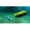
 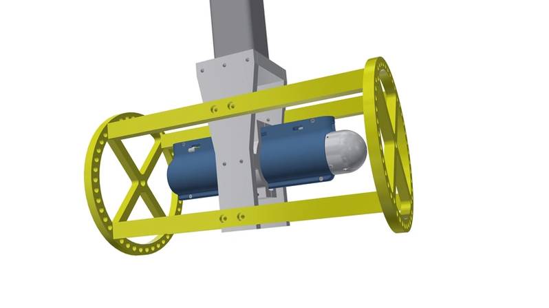 New version of FiGS in and inspection arm 03
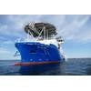
Image courtesy FORCE Technology
Field Gradient Technology
Data quality and value improves through the use of non-contact surveys using field gradient sensor technology. Standard sensors in this field work by detecting potential differences between the Ag/AgCl cells, placed approximately half a meter apart, to gauge anodic and cathodic activities. However, these cells are prone to drifting and necessitate regular recalibrations — typically after every kilometer of pipeline surveyed, or every hour.
There are also weaknesses in terms of accuracy because of signal noise and the ability to detect small field gradients. In this process there is a risk that possible issues like coating damages are not discovered. This can happen because some of the signal peaks are interpreted as noise instead of being picked up as coating damage.
In contrast, a new generation high sensitivity field gradient sensor for use on ROVs and AUVs developed by FORCE Technology employs a novel approach with its electrodes mounted on a rotating head. Called FiGS, the design effectively counters the issue of cell drift and the need for calibration. Moreover, the rotating mechanism enables the sensor to determine the direction of the electric field. This directional insight not only provides a relative positioning for the findings but also ensures that the sensor's readings are consistent, irrespective of the varying positions of the ROV during the survey.
FiGS technology integrates field gradient detection with the measurement of protection levels (potential) using non-contact sensors. The collected data is then merged with CP modeling to provide a comprehensive analysis. This analysis includes accurate predictions of the asset's lifespan, anode current output, and a potential profile, offering a more efficient and thorough assessment of maritime structures' protection against corrosion than possible with stab surveys or dual cell field gradient surveys.
FiGS Operations and Benefits
Conventional approaches to evaluating cathodic protection (CP) systems offer only a momentary glimpse into their status. This limitation compels operators to schedule CP inspections at predetermined intervals, typically every three to five years, or to conduct CP assessments opportunistically when in the vicinity. FiGS, however, revolutionizes this process by providing detailed insights into the lifespan of the CP system. This capability enables operators to tailor survey schedules more effectively, basing them on the residual life of the anodes, thereby optimizing the frequency of inspections and reducing maintenance costs.
The system can also collect data faster than other measurement methods. A FiGS pipeline survey can be conducted with an ROV flying at a speed up to 6-8 km/h without losing valuable information. This is faster than any other advanced CP inspection tool on the market. FiGS can also be positioned higher above the pipeline and still obtain valuable data. The increased speed saves costly vessel time, while the larger measurement distance lowers the risks associated with the flight of the ROV.
Crucially, the system can be used on buried, trenched or rock dumped pipelines, obtaining the same information as for an exposed pipeline. It integrates with active pipe trackers (e.g., TSS440) as the signals from the tracker do not affect the sensor readings. This feature reduces offshore time as a pre-survey with the pipe tracker is not required, resulting in significant cost savings, mainly related to vessel charter.
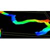
The major advantage of using FiGS on any type of subsea structure is the large amount of accurate information obtained over a relatively limited extent of time. Also, because FiGS data is combined with detailed CP models developed using FORCE Technology’s SeaCorrTM software, it’s possible to easily identify issues such as hotspots including areas of under-protection as well as the impact of CP current drain e.g., to wells, using simple visualizations such as heatmaps. The larger scope, e.g., combining pipelines and structures within a subsea field on one survey mobilization increases the advantages of using FiGS, as all connected assets will affect performance of a CP system.
A complete FiGS report includes; Potential profile plot for pipelines/Potential distribution plot for 3D structures to identify hotspots/areas of under-protection, Anode current output (pipeline and structure anodes), Effective steel current density (including coating breakdown for coated pipelines/structures), Life time expectancy of the CP system in years (i.e. remaining life of sacrificial anodes), Recommended time to next inspection based on condition of CP system, Current drain (from anodes on pipeline/structures to adjacent structures, e.g., drain to well from anodes on X-mas trees), and Coating damages, with position and current supplied.
Another unique aspect is that FiGS data can be used as part of a much wider system that incorporates all pipelines and subsea structures across an entire field. Combined with new cloud-based online reporting and visualization, FORCE Technology can provide a central portal for information on all CP at an entire development or even multiple developments. This can unlock new savings across assets and locations by informing a decades long data-driven maintenance program based on highly accurate lifespan prediction for every CP anode protecting the entire subsea infrastructure.