TEST Simple Integration of Backscatter Processing into a Bathymetry Workflow
Across the various domains of multibeam echosounder mapping, the value of creating quality backscatter maps is gradually becoming mainstream. While it has always been a part of the portfolio for dedicated marine ecosystem surveys, it has only more recently started to become a staple for other surveys such as those conducted for/by Hydrographic Agencies, or surveys in support of wind farm development, as two examples.


The second problem is more complex, and if not properly addressed can have profound effects on the usability of the end products. One of the primary uses of a backscatter map is to create marine habitat maps. The importance of these maps has become critical in supporting decision making at the scientific, commercial and policy levels. Classifying the map into areas of similar backscatter intensity results in a representation of the boundaries between different seabed sediment types. The automatic classification process is however highly dependent on a quality backscatter map, and any issues with the map such as the presence of artifacts, poor contrast or low signal to noise ratio, can all compromise the fidelity of the classification.
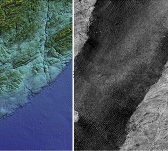
Figure 1: Example backscatter map draped over the bathymetry.
When looking at the two problems together, we converge on the need to have dynamic algorithms which adapt to various changes in the acquisition environment, and those algorithms need to be able to adapt autonomously to allow them to be run as part of an automated workflow which the user will not need to rerun several times while tweaking and adjusting settings.
Over the past few years Teledyne CARIS has implemented several significant improvements in the SIPS Backscatter engine, specifically addressing artifact issues related to beam patterns, gridding and Angular-Varying Gain (AVG) corrections. The beam pattern process has been adapted to automatically create new sections based on changes to the sonar settings. The beam-based gridding algorithm has been replaced by a method more suitable for time-series and multisector data and is less prone to interpolation artifacts. Finally, the per-line AVG correction has also been adapted to become area-based, therefore reducing the line overlap effect.
Multi-mode Beam Pattern
The SIPS Backscatter engine applies several radiometric corrections to the recorded backscatter samples. This includes corrections for Time Varying Gain, transmission and reception gains, ensonified area, normalization, and the beam pattern correction. Focusing on the beam pattern, there are various approaches to computing the correction. A popular approach is the manual selection of a homogenous area of seabed, however this has the drawback of requiring manual user interaction and it is highly sensitive to what section of seabed is selected. The approach originally employed in the SIPS Backscatter engine was to use all data as an input to the beam pattern estimation process, under the assumption that with enough quantity and variety of input data, the contributions from different angles of incidence and bottom type should average out and converge to a clear beam pattern. One of the key advantages to this approach is it allows the process to be automated, but having a single beam pattern for the entire dataset is not always appropriate.
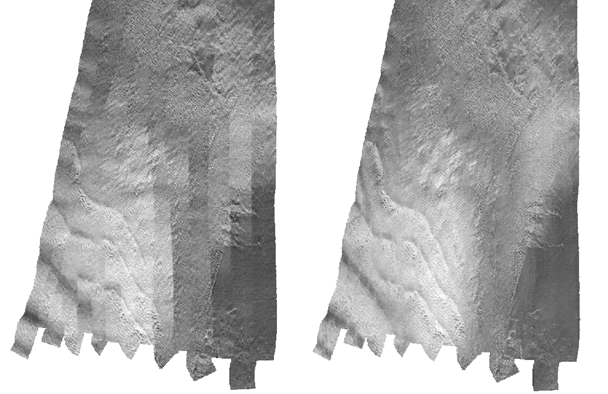
Whether triggered by operator changes, or as a part of automated systems within the sonars, it is common for there to be changes to the waveform and pulse length during a survey to allow continuous collection of optimal bathymetry throughout the entire survey area. Each combination of pulse length and waveform, in addition to each sector of a multi sector sonar, has its own distinct transmission and reception characteristics resulting in the need for a unique beam pattern for each case, referred to as an acquisition mode. Therefore, the beam pattern estimation process for SIPS Backscatter has been enhanced to automatically handle dynamic steered sectors and changes in pulse length / waveform throughout a survey by creating a unique beam pattern for each acquisition mode. The process automatically groups pings into their common groups before feeding all pings within the group to the beam pattern calculation. Figure2 shows an example on a single line. The left image is using a single beam pattern and shows distinct along and across track artifacts as the pulse length changes. The image on the right employed the multi-mode beam pattern with the result being a vastly improved map.
Figure 2: (Left) Corrected with single beam pattern. (Right) Corrected with multi-sector beam pattern
Area based AVG
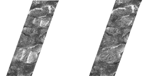
A traditional AVG correction is computed from an along track stack of pings and applied locally to individual lines. Although this did fit nicely in the existing line processing workflow and gives satisfying results within a single line, the problem with the approach is that areas of overlap between lines will receive a different correction. When there is strong variation in the seabed composition it can create across-track artifacts like the ones we see on the map in Figure 3 (left).
The SIPS Backscatter algorithm has been updated to move to an area-based approach which utilizes any overlapping information to compute and apply the AVG correction. With the new algorithm, the computation of the AVG corrections is made by sliding a small window across the datasets along both axes. The samples from all lines in the small window will receive the same correction which is calculated from a larger contributing area around the window. The overlap created by the larger contributing area ensures a smooth transition across the dataset. The new area-based AVG correction allows high quality backscatter maps to be produced as can be seen in Figure 3 (right).
Figure 3: (Left) Corrected in HIPS and SIPS with line based AVG. (Right) Corrected in HIPS and SIPS with area based AVG. Data source: UK Environment Agency.
WMA Gridding
The gridding engine behind SIPS Backscatter has also been updated to a new Weighted Moving Average (WMA) technique, with two primary design factors: weighting and search radius. The weighting function was designed to take into account both the inverse distance of each sample from the grid node, as well as the beam position within the swath (nadir vs external). The search radius is designed to allow the user to choose between using the grid resolution or the beam footprint, along with a multiplier.
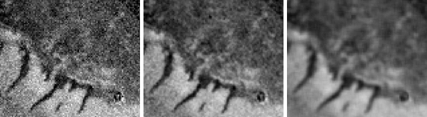
While WMA gridding is a well understood standard for bathymetry processing, making use of WMA in the creation of backscatter maps has added several benefits to the resulting products. The main benefits are its ability to respect the geometry of multibeam echosounders and preventing over-interpolation of data. A secondary benefit is in the way that the search radius now provides a simple control over the amount of smoothing applied to the backscatter map (Figure 4).
Figure 4: Demonstration of the effect of changing the search radius multiplier. From left to right search radius = (0.5, 1, 2.5) x beam footprint,
Conclusion
These state of the art algorithms which are capable of automatically adapting to your data, whether that be dynamically adapting to changes in acquisition settings, or strong variations in the seabed composition, have all been built on the CARIS automation framework, and are available to be run in CARIS Onboard 2 and HIPS and SIPS 11 alongside your bathymetry processing. By combining these dynamic algorithms with the ability to be run as a single additional automated process at the end of your bathymetry workflow, HIPS and SIPS provides a solution to modern needs. In most cases high quality backscatter products can be produced simply by running a single process at the end of your bathymetry processing workflow, making the addition of backscatter processing to your bathymetry workflow an easy step to help meet the needs of the evolving ocean industry.