Lander Lab #4: Underwater Releases
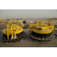
10) on both sides, providing the same capability in a small lander. (Illustration: ORE/EdgeTech)The ring link is connected to the anchor weight by a second chain.When either end of the release chain is dropped, the buoyancy of the lander causes it to rise, while the negative weight of the anchor chain causes it to drop. The release chain continues to pull through the ring link that is attached to the anchor chain until it is free.The Elegance of SimplicityAs entropy describes a gradual decline into disorder, Murphy’s Law defines a "seemingly spiteful behavior manifested by inanimate
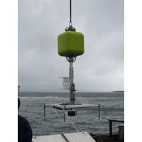
Anti-Fouling Film Tested on Fairway Buoys
;m impressed,” says Böning, “If further long-term practical trials are equally positive, we will be able to cut overall operating costs by reducing the frequency of inspection trips to the buoys”.*The small amount of fouling which is seen on the picture, is only located on the anchor chain which does not count to the part of the buoy which had to be wrapped
The Hunt for the Notorious U-Boat UB-29
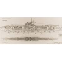
landing craft, like the ones in Saving Private Ryan. So it didn’t sound very interesting.” Modern multi-beam echo-sounders—the sonar devices now used for hydrographic surveys—are far more sensitive than earlier technologies. “Today you can almost see the links in an anchor chain. This was obviously not a landing craft. It wasn’t shaped like a biscuit tin, but like a cigar, with two pointy ends and a tower in the middle. The surveys also give you the length, and this was 26 or 27 meters. I was like, Bloody hell! This has to be a submarine!”The original faulty
Mooring Installation Highlights Thordon's Range
, making the buoys easy and quick to install. Single or multi-path swivel stacks can also be fitted with utility swivels to power and control subsea valves.For each of the buoy’s chain stoppers Wenex recommended 32 abrasion-resistant ThorPlas-Blue bearings, due to their ability to pivot with the anchor chain. Thordon also supplied 16 SXL entry chafe bushings that were installed to provide a greater level of wear resistance to the anchor chain, while 32 SXL thrust washers were supplied to help reduce the side-to-side motion of the Calm Buoy during inclement operating conditions.“There is a willingness
Surveyors Search for WWII ‘Highballs’
by personnel from GSE Rentals who had provided the winch, cable and ancillary support for the project. An initial pass through the centre channel of the Loch revealed the seafloor was made up of a relatively featureless area save for extensive trench-marks and scarring presumably caused by the anchor chains used by large cargo container traffic that at one time used the loch as a safe haven during poor weather. On approaching the area nearer the location of the target ship it was discovered that one or two Highball devices had clearly fallen short of the Courbet and it was suggested that
Load Cells for Offshore Mooring Project
product for measuring tension on lines, the Running Line Dynamometer (or TIMH), specifically built with dockside, marine, offshore, towage and salvage applications in mind. However, as David Mullard, SP business development manager, explained, “the TIMH wouldn’t have been suitable because anchor chain was being used rather than wire rope. Wire rope can bend, allowing it to pass through the sheaves of the TIMH so that a tension measurement can be calculated. The large dimension chain wouldn’t have allowed the same thing to happen,” he said. Pierre Recoules, project manager
Hook-Up Operations Added to QINSy
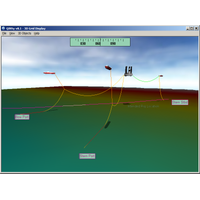
all have their own structural characteristics. The Hook-Up functionality is added in the Session Setup of the QINSy Controller, were the Hook-Up operation is added as a new operation type. The operation can be visualized in 3D using the QINSy 3D Display. The catenary of the anchor chain and wires are displayed as well as the distances between the seabed and the deepest point of the catenary and between subsea assets and the catenary
New Software from EIVA
that covers both operation planning and execution, designed to simplify the work process and reduces the risk of calculation errors that comes with using multiple software tools. The advanced catenary algorithm behind the catenary feature of NaviSuite Beka offers high-performance, virtually instant anchor chain catenary simulation. The algorithm computes the physical behaviour of the defined anchor chains taking into account material weight, drag, buoyancy, elasticity, etc. Also, as it is a 3D algorithm, it takes into account water currents, among others. www.eiva.com (As published in the MAY 2015
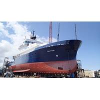
Markey Equips Research Vessel Sally Ride
are powered by single 30 HP electric motor. The system is rated to pull 26,500 lbs. at 205 ft. /min and light line pull of 16,500 lbs. at 300ft/min. Finally, but certainly as important, the Sally Ride uses a Markey type WES-23 two wildcat electric anchor windlass to handle 1-7/16” grade 3 anchor chain. Designed for bolt-down installation, each wildcat on the WES-23 is fitted with a band-type brake, a jaw-type disconnect clutch and two 18” diameter warping heads at each end of the horizontal main shaft. The WES-23 is driven by a 30HP, NEMA-D marine motor that is rated for 30-minutes of