Lander Lab #4: Underwater Releases
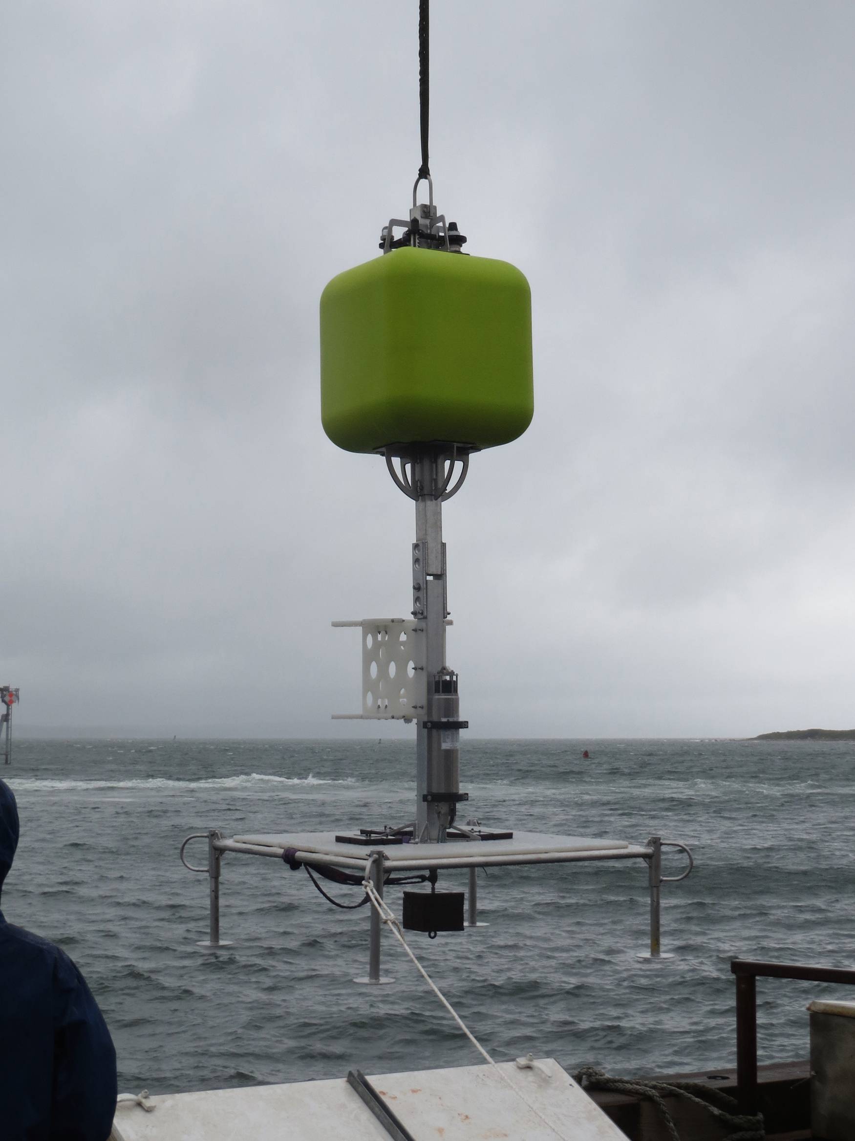
Figure 1. Schmidt Ocean Institute benthic lander is deployed from R/V Falkor for an operational test. Syntactic flotation high, integrated acoustic release low, and the expendable anchor weight suspended below the platform deck. The negative weight of the release is placed close to centerline for trim, and positioned low to act as a counterweight for stability. No instruments are mounted on the white marine grade HDPE frame. The anchor weight is rigged for recovery after the test. (Photo by
“We can get anything to the bottom of the ocean,” quipped Don Walsh, Pilot #1 of Bathyscaphe Trieste. “The trick is getting it back.” A release is how we get our lander back. The anchor weight needs to be discarded, allowing the self-buoyant lander to float back to the surface. That’s the primary task of a release.
Releases serve other secondary purposes. They are used to initiate action such as deploying a drop arm, closing a water sampler or animal trap, or releasing a surface buoy or hydrophone string.
A clever at-sea adaptation of timer releases was reported by Scripps researchers Mantyla and Reid in 1977. Making measurements of salinity, oxygen and silicates in the Mariana Trench, they found the tapered wire rope on the hydrographic winch was of insufficient length to reach below 10km. Engineer Dave Muus proposed modifying a John Issacs “Monster Camera” free vehicle, a chain of components more like a short mooring than an ocean lander, to carry a string of Niskin bottles. A timer release of the messenger was set to occur 30 minutes after ETA on the seafloor. A second timer release was set to drop the anchor 10 minutes later. Dave rigged and deployed the free vehicle. It worked. Researchers found secondary benefits: the vehicle descended and rose twice as fast as the winch payout and inhaul, while the water samplers could be placed much closer to the bottom. They rigged and deployed a second time. It worked again.
Releases are available both as commercial products, and in-house customized solutions. They can be sorted into functional categories: Acoustic, Timer, Magnetic, Electrolytic, Galvanic, Fusible Link, Pressure, Melt and Dissolvable.
Expendable electrical release elements can be a burnwire (aka corrosive link, galvanic link) and fusible link or “flash wire”.
A release can be broken down into a handful of elements.
- There’s the trigger that starts the release function, such as a countdown timer, acoustic command, bottom contact, or event sensor.
- There is the load bearing release element. This could be a burnwire, a flash wire, a rotating thread, a rotating rod with a semicircular segment on the end, or a retracting plunger. This in turn may release a force multiplier, such as a lever or pelican hook.
- There’s the power source, usually batteries, which could be supplemented by compressed air or squib gas generating cartridge.
- There’s the housing, a sphere or cylinder.
Acoustic Releases
Today many commercial acoustic releases are available.
Most commercially available releases come as a fully integrated package, such as the EdgeTech 8242XS. The design allows the in-line load to be taken directly though the release housing. In-line tension is routed around the hydrophone by a heavy metal cage on the top. The cage also serves to protect the ceramic transducer from impact. The transducer is placed on top to provide a clear view to the surface for acoustic communication.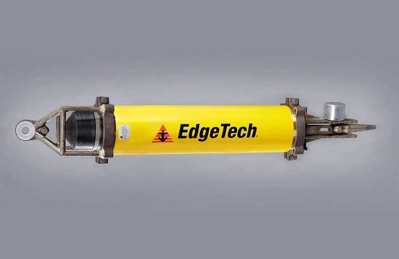 Figure 2. The EdgeTech 8242XS acoustic release. (Photo by Edgetech)
The release can be dualed with a second release, providing a back-up for critical functions, or paired with a strong back to substantially increase the load rating from 12,000-lbs to multiples higher. Typical lander anchor weights, however, are under 100-lbs, so the size, cost and weight are a little overkill. Some consider rotating shaft seals to be a weak point, though I’ve never seen those fail in the scores of sea trips I’ve been on.The release also functions as a transponder, providing a ranging function. Anyone who’s been to sea will agree that’s another benefit: one ping means a lot when it’s coming from the bottom of the ocean.
Acoustic releases have an immense set of unique transmit/receive frequencies, command codes, and multiple frequencies to negate ambient noise fields, making them safe to use within acoustic range of each other. It’s wise to make a chart of manufacturers, release codes and frequencies then comparing those, especially if multiple groups are involved in a joint operation.
Acoustic releases are preferred for long term deployments, where the lander remains safely on the bottom until the ship returns. This allows for changes to ship schedules, bad weather, unexpected ship problems, crew health, plus Murphy and his prankster friends.
The top side part of an acoustic release is a matching deck communications box with overboard hydrophone.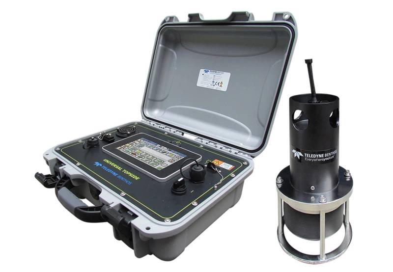 Figure 3. Teledyne Benthos UTS-9500 Universal Topside, an acoustic release deck command unit and overboard hydrophone. (Photo Teledyne Benthos)Manufacturers of the integrated acoustic release design include:
- Applied Acoustics
- Desert Star Systems
- develogic GmbH
- EdgeTech
- iXblue
- Teledyne Benthos
- Sonardyne
- Subsea Sonics
Downsides include this type of release can be heavy, with a water weight of up to -62 lbs, limited to 6km (Benthos has a 12km version), and only a single release function. The air weight is 79-lbs, plus the weight of a 17” glass sphere to lift it (+57-lbs buoyancy, 51-lbs air weight), then add additional buoyancy, counterweights, scientific payload, and the frame to tie all together. The assembled weight of the lander on deck becomes something more than can be hand deployed, suggesting the larger release designs are better suited to moorings than small landers.
For shallow water, long term deployments, biofouling of the release mechanism can compromise a clean release. EdgeTech developed alternative release techniques including a “push-off” mechanism, where a threaded shaft unscrews a threaded link (PORT-LF) that holds the anchor weight, and a dual burnwire release (BRT-6000).
SubSeaSonics <www.subseasonics.com> offers a lightweight, low cost, 300m acoustic release, model AR-60. Anchor release is via electrolytic erosion of a burnwire with a maximum load release of 200 lb (91 kg).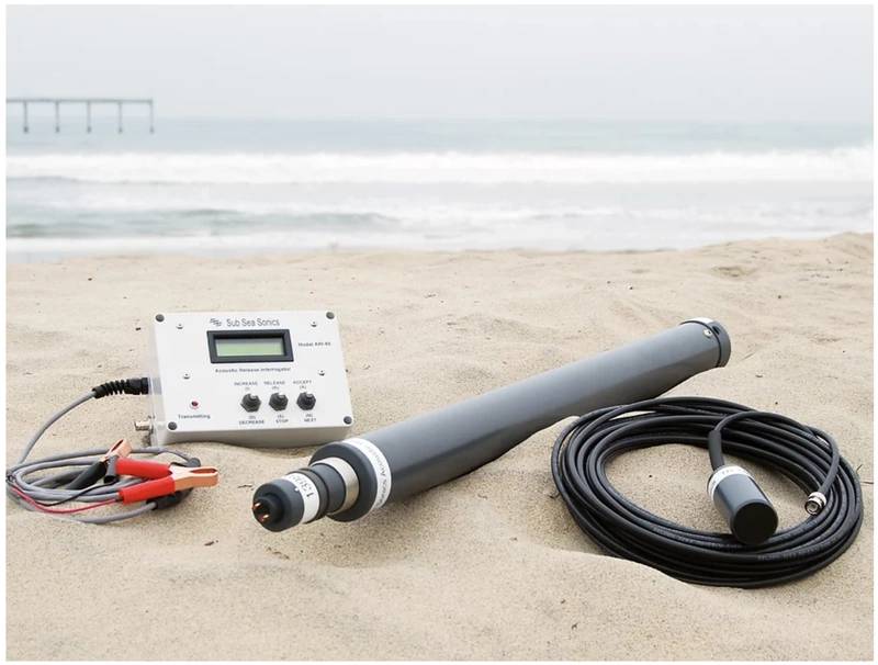 Figure 4. The SubSeaSonics AR-60 acoustic release with deck command unit and overboard hydrophone. (Photo by SubSeaSonics)
The basic elements of an acoustic release can be dispersed to their optimum locations: load bearing element at the bottom, transducer at the top, electronics and batteries mid-body, all connected by underwater electrical cables.
One favorite of solution of mine is to house an EdgeTech circular BART (Burnwire Acoustic Release Transponder) board with dual burnwire release inside a Nautilus Marine Service Vitrovex glass sphere. It’ll easily fit in a 10” sphere, rated for 10km. A thick wall 13” or 17” sphere will provide full ocean trench rating, and more buoyancy. The LF (low frequency) transducers provides stable communication to the deepest ocean depths. This adaptation provides access to 4 additional BART commands, including two additional burnwires, plus two toggle-on/toggle-off control lines in a buoyant housing.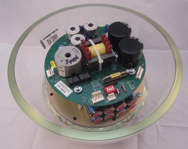 Figure 5. An EdgeTech circular BART board fits nicely inside a 10-in. Vitrovex glass sphere. The adaptation by Global Ocean Design has been used to 11km depth by multiple institutions. (photo by Kevin Hardy)Timer Release
A countdown timer is programmed for a predetermined time-until-release (TUR). The hours and minutes are calculated from a specific start time until the release function should begin. Carefully calculate elapsed time, and make good log entries of expected release time, programmed elapsed time, and actual start time. Smartphone pictures will help. Add 10 minutes for the burnwire corrosion, plus 1m/sec rise time for an approximate time when the lander will break the surface.
The SubSeaSonics TR-45 is the only commercially available underwater timer release I am aware of. The release unit contains a microcomputer and batteries. It has a replaceable burnwire link with a screw-on retainer cap.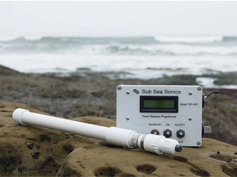 Figure 6. The SubSeaSonics TR-45 Timer Release with on-deck programmer. (Photo by SubSeaSonics)System advantages include low cost, up to 170 days of deployment, and the ability to program the timer without opening the case. The system is limited to 180m depth, and its single strand burnwires look to be sensitive to sideloading and torque. Global Ocean Design adapted the SSS timer to retain the best features, adding the capability of charging through the endcap, increasing the power for heavier burnwires, and using spherical or cylindrical housings for up to full ocean depth. A single high-power TR-45 is available in a 7075 Al housing rated for 11km.
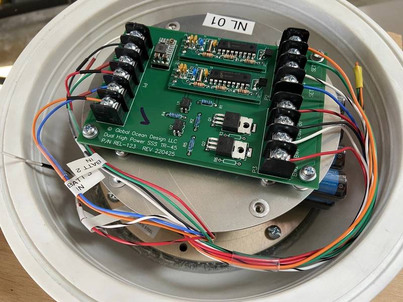 Figure 7. The modified twin SubSeaSonics TR-45 timer boards provide a dual high-power release in this adaptation by Global Ocean Design. (Photo by Kevin Hardy)
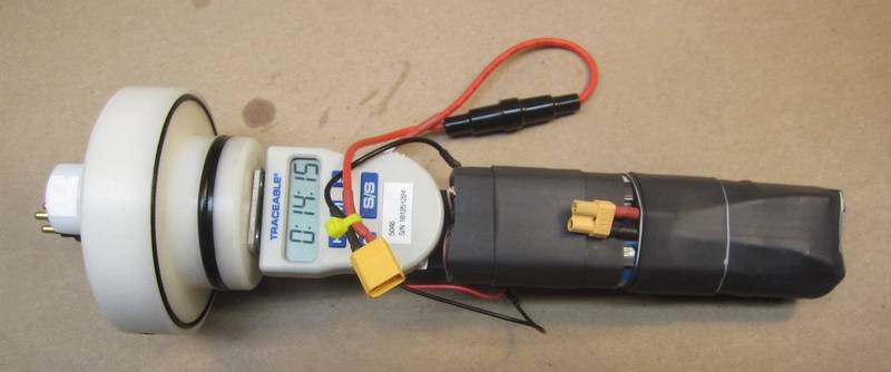 Figure 8. A 100-hour scientific countdown timer is adapted for a time release. The 1.5vdc signal that powers the beeper is used as the gate input to a SCR. The 9.6vdc NiMH battery pack supplies power to a burnwire. Similar timers in 7075 aluminum housings have been used to the bottom of the Kermadec and Tonga Trenches. (Photo by Kevin Hardy)
Magnetic Release
A clever magnetic release uses two disks with embedded sets of neodymium magnets, arranged N-S-N-S. The concentric plates attract in one position, then one rotates 90° to repel the other. The design was successfully implemented by Victor Villagrán, University of Concepción, Chile.
Recall the Trieste used iron shot and an electromagnet for a release. That design takes continuous power, but perhaps the iron core of the electromagnet will attract a neodymium magnet until the moment it is energized. Be fun to try.
An electromechanical solenoid is a form of magnetic release, used successfully in the deep ocean since the 1960’s with Frank Snodgrass at Scripps. They can be susceptible to biofouling at shallow depths, but should work to hadal depths as the coil is potted or oil filled, and the iron shaft is free floating with the coil.
Electrolytic Release
Burnwires
A “burnwire” doesn’t really burn, it’s an electroplating process. Metal is extracted from the anode (burnwire) and plated onto the cathode. In practice, a waterfall of rust flows out of the burnwire, cascading downward. A burnwire provides tremendous mechanical advantage, holding hundreds of pounds, but corrodes with as little as 5 vdc. Higher power systems run 10-21vdc. An in-line burnwire has no moving parts, and is inherently reliable.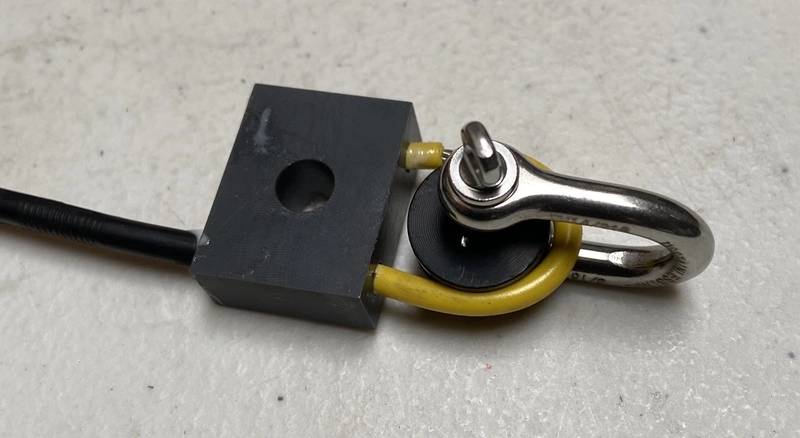 Figure 9. A Global Ocean Design REL-238 burnwire. The Delrin spool maintains the minimum wire rope bend radius. The exposed wire rope is just behind the shackle. (Photo by Kevin Hardy)
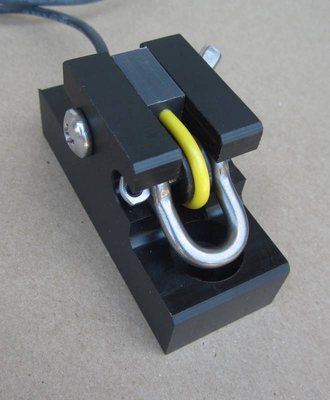 Figure 10. The Global Ocean Design burnwire mount with burnwire. The burnwire is kept from rotating and protected from side loading. On release, the shackle pulls straight out the bottom. The burnwire mount also fits the EdgeTech burnwire, both single and double strand. (Photo by Kevin Hardy)
The simplest burnwire release I ever made was three parts: a 9.6v NiMH battery with the positive terminal tied to the burnwire (think “sacrificial anode”) and the negative terminal tied to a cathode (think “cathodic protection”). The switch was the air gap. I had to pull the suspended anchor weight into the interior of a lander for deployment, then have it drop out and suspend below the lander before it reached the bottom. As soon as the lander hit the water, that burnwire started. The scheme worked.
Burnwires can be expensive, but lack of practice or training can be more so. Experience provides confidence and competence. A simple solution is to make “training burnwires”. These are a 12” length of jacketed stainless steel wire rope (JWR), one end stripped about 3/8” for electrical connection, the other end sealed with a layer of marine grade heat shrink, overhanging and pinched flat on the end to seal it. The center of a heavy steel hex nut, like a ¾-16 thread, is filled with 5-minute epoxy. After the epoxy sets, drill a center hole through the epoxy that is larger than the JWR OD, but smaller than the OD of the heat shrink. Then slip the nut on the JWR from the stripped end. It should rest on the marine grade heat shrink. Add another layer of heat shrink if needed. Mark a spot on the JWR about ½” above the hex nut. Remove the hex nut and strip a narrow gap 1/8” wide around the JWR, exposing the SS wire beneath. Replace the hex nut weight. The training burnwire can be suspended in a bucket of seawater until the 1/8” gap is fully immersed. The JWR can then be taped or clipped to a cross bar spanning the bucket. The stripped end is connected to the burnwire terminal of the release. A stainless-steel welding rod, placed in the bucket as a cathode, is connected to the cathode terminal of the release.
Single strand burnwires are more prone to work hardening from sideloading and torque than multistrand wire rope. This may cause the wire to break and drop the anchor at an unplanned time, so restraining those elements with a mount is important.
A burnwire must be mechanically connected to, but electrically isolated from, the steel drop chain.
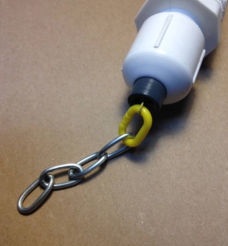 Figure 11. A SubSeaSonics LK-80 release link electrically isolated from the steel chain with a plastic link. (Photo by Kevin Hardy)
If a burnwire is electrically connected to a steel drop chain, electrical power intended for the burnwire will be wasted as it attempts to corrode the length of chain. Whether made commercially or in-house, it’s good practice to perform a simple load test to be certain there are no fabrication flaws that would compromise performance.
Shackled end-to-end, several can be tested at once, hanging from a freestanding ladder, using a bucket of sand as the load. Some manufacturers do this before shipment.
Another handy design rule is there is no practical limit to the distance between the anode and the cathode. I’ve placed burnwires 15-ft from the cathode without problem.
Galvanic Timed Release
• International Fishing Devices US <https://www.underseareleases.com/techspecs.htm>
• Ocean Appliances AU <https://oceanappliances.com.au/>
Galvanic Time Releases (GTR) are driven by the potential difference between dissimilar materials in seawater, in this case anode grade zinc and stainless steel.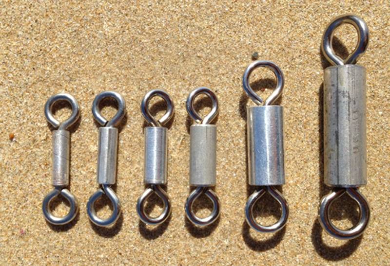 Figure 12. Galvanic time releases (photo Ocean Appliances, Australia).
The Galvanic Timed Release has only three components: two cathodes and one anode. When the GTR is placed in an electrolyte such as seawater the cathodes, a more noble metal, cause the cylinder of less noble metal to electrochemically disintegrate.
The simplicity of the design makes them very inexpensive: about $3 each.
International Fishing Devices advertises a standard accuracy of +/- 2.5% of the release’s designed duration, but can increase the GTR's accuracy to within +/- 1%. The standard GTR is designed to be used under tension loads of approximately 10-lbs for 1-7 days. With the utilization of mechanical advantage, the standard GTR will restrain loads of up to 1,500 lb. Durations of 17-100 days and loads up to 1,000-lbs are also possible.
Fusible Link (Flash wire)
Developed by DesertStar for their ARC-1 acoustic release, a large capacitor is fully charged, then power dumped through a high resistance nichrome wire, causing it to instantaneously vaporize. Sometimes called a “flash wire”, the ARC-1 triggers just 10 seconds from the release command, and the trigger process itself takes just 0.03 seconds. The ARC-1 has only a single moving part, making it very reliable. Biofouling would not be a concern for the flash wire, though it may gum up the lever arm. It also operates in fresh water. Since its introduction, the system has accumulated tens of thousands of release cycles.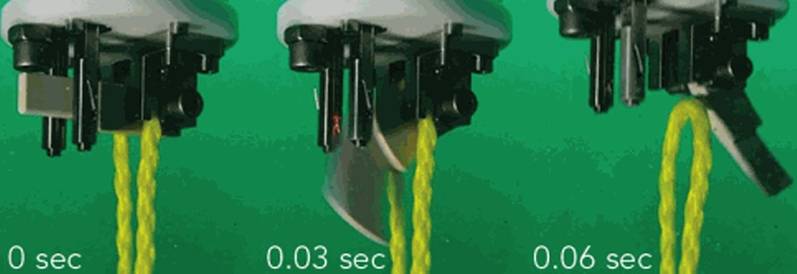 Figure 13. Featuring the fastest release of any release system, DesertStar’s ACR-1 opens in under a 1/10 sec. (Photo Desert Star Systems)
One can imagine the combination of a flash wire release, pressure sensor, and programmable controller for bottle closure that would allow the collection of water samples at precise depths by a free-ascending lander, now a profiling vehicle. A series of CTD casts could occur quickly with a small number of untethered free ascent rosettes.
Pressure
The trigger is pressure. This is a sensor that activates a circuit at pre-determined depth, or a mechanical element that reacts to increasing ambient pressure in such a way as to initiate a release.
Melt
Hot wire
Weed whacker nylon cord or heavy monofilament nylon fishing line can directly attach an anchor weight to a lander frame. Crossing the monofilament like a bow on a cello, is a length of Nichrome wire. Current through the wire causes the nichrome to heat up, slicing its way through the nylon. Performance may be improved with thermal insulation from the environment.
Ice
Ice has a very high compressive strength, as evidenced by Titanic’s head-on collision with that iceberg, or a USAF C-130 cargo plane landing on an Antarctic ice sheet. 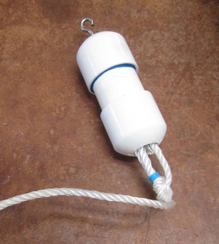 Figure 14. Standard 1” sch 40 PVC pipe makes an ice release that will hold 300-lbs for up to an hour. An eye bolt passes through the top cap, with a flat washer and nut on the interior, and sealed with RTV. A slot at the bottom allows for a loop of line to be inserted. The release is then turned with the slot up, filled with tap water, then placed in the freezer. (Photo by Kevin Hardy)
As a result, ice makes an easy, cheap, and strong release capable of holding up to 300-lbs. Enclosed in the thermally insulating PVC, the release can take up to an hour to release. The ice will definitely melt, so a release is assured, though time may vary with water temperature.
Dissolvable
Lifesaver
I remember reading an in-house technical brief shared with me by Scripps machinist Mert Ingraham, written by a Scripps grad student in the 1960’s describing the use of Lifesavers as a release. That student used a lever arm to multiply the force to hold a larger anchor.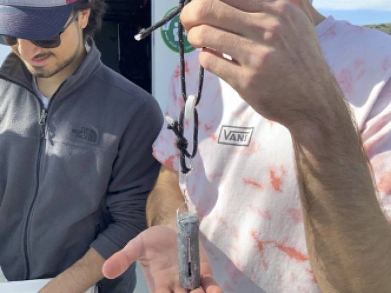 Figure 15. Cal Poly-San Luis Obispo undergraduate students Mason Gariepy and Kyle Walsh test a Lifesaver release used to deploy a baited arm on their lander DOV SEASTANG. (Photo by Nikki Arm and Brianna Roberts.)
I shared that idea in recent years with two Scripps graduate students and an undergraduate team at Cal Poly-San Luis Obispo as a means to hold a baited drop arm in a retracted position during their lander launch and descent, then release the arm to rotate down to the seafloor. They each adopted the idea and found it worked fine. In a careful study, the Cal Poly students found all colors of lifesavers could hold up to 10-lbs (all broke at about 20-lbs), and would release between 17-25 minutes in flowing water, depending on the weight being carried.
3D printing filament
3D printing uses two kinds of filament. One for mechanical strength of the final part, and another to create support structure as the part is being made, if required. The support material must be removed from the final part before it is put into use. The support material Polyvinyl Alcohol (PVA) is removed by water immersion. Dr. Bart Chadwick, then a scientist at the USN SPAWAR laboratory on Point Loma, suggested PVA filament might be used as a dissolvable release link.
It’s been tried by some, I understand, though I have not heard how it worked.
Once the release element is chosen, adapting it to a lander presents other choices.
A force multiplying lever can be used to increase the load carried by a given burnwire or release element. A pelican hook for example, is really a Class-2 lever, where the load and the restraining force are on the same side of the fulcrum.
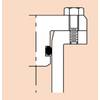
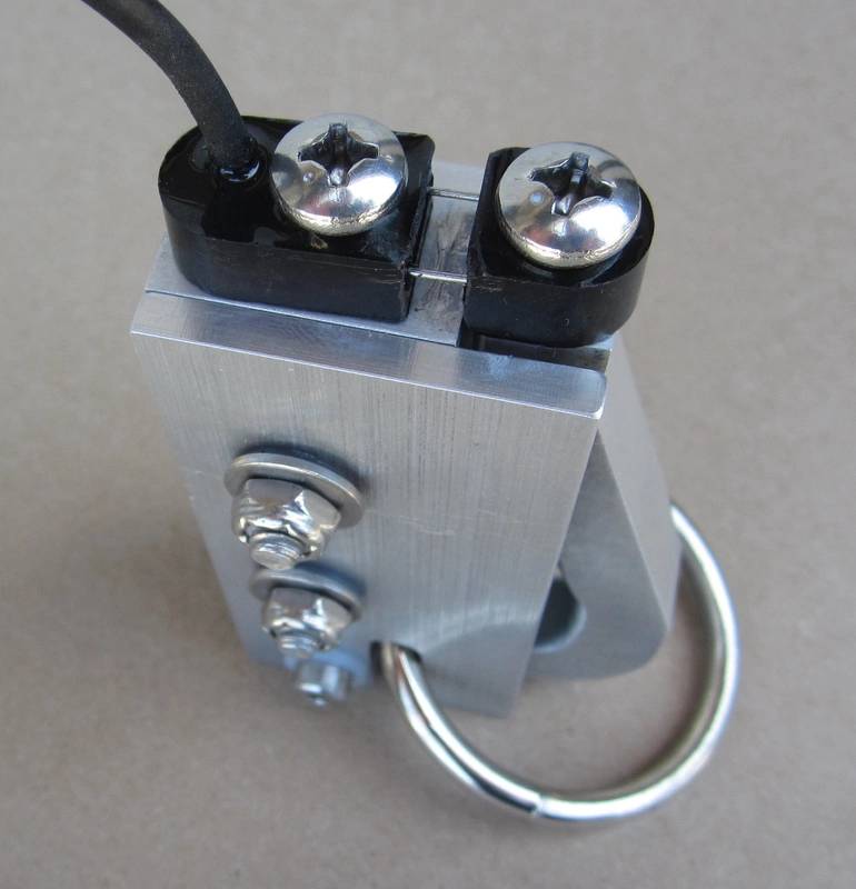 Figure 16. An EdgeTech burnwire, rated for 100-lbs, can restrain a load of 500-lbs using the mechanical advantage of a Pelican Release. (Photo by Kevin Hardy)
Two releases may be used to hold a single anchor weight, providing a back-up release capability.
The ends of a “release chain” connect the two releases, forming a “V”. With one end loose, a large steel ring link is placed on the release chain. The ring link is comfortably larger than any link or shackle required by the release that maybe on the end of the chain.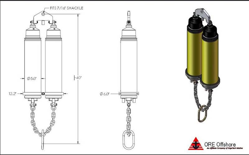 Figure 17. An example of a dual release arrangement sharing the load of the anchor, and providing a back-up release for critical applications. Landers can have burnwire mounts (Figure 10) on both sides, providing the same capability in a small lander. (Illustration: ORE/EdgeTech)
The ring link is connected to the anchor weight by a second chain.
When either end of the release chain is dropped, the buoyancy of the lander causes it to rise, while the negative weight of the anchor chain causes it to drop. The release chain continues to pull through the ring link that is attached to the anchor chain until it is free.
The Elegance of Simplicity
As entropy describes a gradual decline into disorder, Murphy’s Law defines a "seemingly spiteful behavior manifested by inanimate objects" brought about by “malignity of matter, the total depravity of inanimate things, whether the exciting cause is hurry, worry, or what not.”
At an 1877 society meeting on steam boats, engineer Alfred Holt, reported, “It is found that anything that can go wrong at sea generally does go wrong sooner or later, so it is not to be wondered that owners prefer the safe to the scientific … Sufficient stress can hardly be laid on the advantages of simplicity. The human factor cannot be safely neglected in planning machinery.”
Whatever release design you adopt, keep the part count to a minimum and the path for moving and releasing parts to be as clean as possible. Simplicity of design embodies reliability. KISS: “Keep it Simple, Sailor.”
Shop Talk:
In the category, “I haven’t tried this yet, but it should work…”
We know when a timer release functions, the anchor drops and the lander rises to the surface. There is no signal from the lander that the release is in progress. Topside, there’s only the knowledge that the timer was set correctly, and was counting down when it was deployed. On the day of recovery, we hang out and wait at the prescribed time and place. Allowing for burn and ascent time, we scan the area around the boat, waiting for the lander to appear. First guy to spot the flag gets bragging rights. It’s not a precise time, so we learn patience if it’s a little late.
Similarly, imagine a receive only/no reply acoustic release using a Smartphone with a playlist called “Releases”. Each release command is downloaded as an MP3. At the prescribed place, the output of the smartphone feeds into a signal amplifier, then to an overboard hydrophone. We send the command, and hang out and wait, allowing for burn and rise time. This is XMT only, no RCV. There is no signal from the lander that the release is in progress. We scan the area around the boat, waiting for the lander to appear. First guy to spot the flag gets bragging rights.
Such a system would cut the cost of the deck unit, while providing the advantage of releasing on command rather than a preset time, providing the scientific crew some flexibility with weather, ship, and personnel.
For further information on acoustic releases and how they function, please visit “Discovery of Sound in the Sea” (DOSIT).
Ocean scientists once had to rely on clever hacks of everyday items for release mechanisms. These can still be useful, but new options have come around.
Cut18_Pliers release
Figure 18. A wire-plier release mechanism. The magnesium wire has a diameter of 1.5 mm. The pliers have a single joint. The serrations inside the circular pipe grip of the jaws have been drilled out. When the magnesium wire dissolves in seawater by galvanic action, the spring pulls the pliers open to release the weight. (Illustration, Phleger et al., 1970)
Acknowledgements
The author thanks Greg MacEachern and Rob Morris, EdgeTech, Gary Burnhardt, formerly with Benthos, John Kemp, WHOI, Frank Snodgrass and Bob Truesdale, formerly from Scripps, Le Olsen, formerly of UW-APL, and Bart Chadwick, SubSeaSystems for their advice with applications, willingness to try new things, and always sharing from their wealth of experience and knowledge.
Reader Feedback
Your comments and shared experiences are always welcome. Please send your thoughts, stories and photos to: Kevin Hardy [email protected] … you may find yourselves in print.