O-ring Seal Design, Part 2: Radial Seals for External Pressure
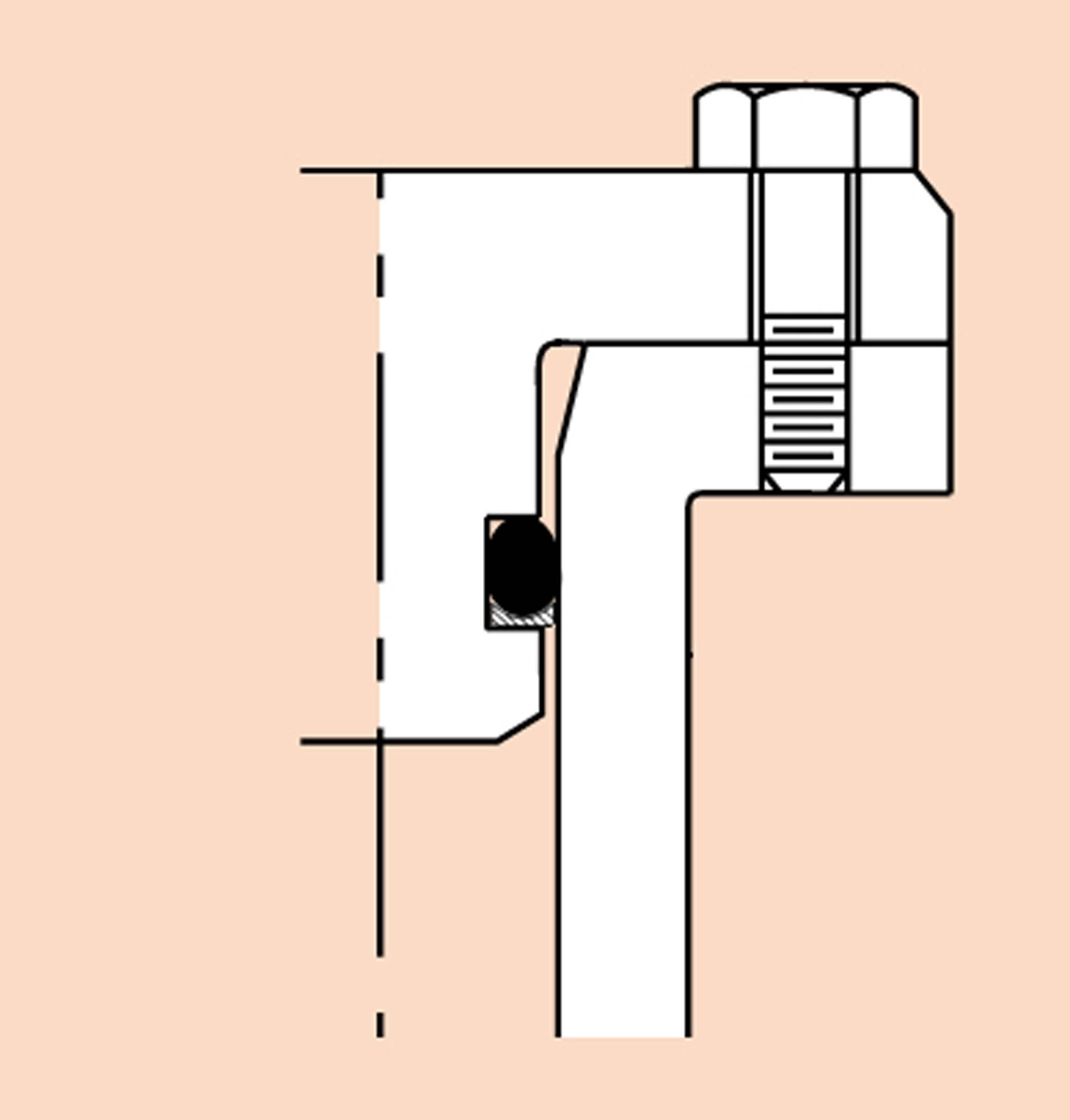
Figure 1. An o-ring is shown in a radial groove with the endcap secured. Note the use of a back-up ring and lead-in chamfers. (Image courtesy Parker Hannifin, adapted by the author for this article)
Ocean engineers are first tasked with keeping the water on the outside. A breach in the hull can mess-up a good day at sea.
Our discussion of o-ring seal design began with a look at Face Seals in the Marine Technology Reporter, Jan/Feb 2026, pp. 20-23.
There is important background and basics in that article that relate just as much to this article, but not fully repeated here. To summarize those basics:
- There is no better design reference for o-ring seal design than the Parker O-ring Handbook (ORD-5700). A pdf is available to download for free (See “Citations” below). It is mandatory reading for ocean engineers, and contains much more detail than possible in any article.
- The o-ring seal creates a barrier to fluid flow. The o-ring seal assembly consists of an o-ring captured in a groove.
- Assembly lubricants should always be used sparingly. They are used to decrease friction and allow the o-ring to respond to pressure and move inside the groove.
- The leading cause of o-ring failure is extrusion through a gap.
- A Radial seal requires a gap to assist with assembly that the Face seal design does not.
A Radial seal is chosen when: 1) there is limited flange area for a face seal and endcap retaining bolts, or 2) as a secondary back-up seal to a primary face seal. Occasionally, two radial seals are used. The first seal to see pressure is the primary. The second seal to see pressure, in the event of the failure of the primary, is the secondary.
O-ring stretch: If the ideal design groove is in between two o-ring sizes, you can stretch the smaller o-ring to fit the larger groove. You can make a smaller o-ring larger, but you cannot make a larger o-ring smaller. When an o-ring is stretched on installation in the groove, the cross-section is flattened. Beyond 2-3% of stretch, the groove depth must be reduced to retain the necessary squeeze. Parker recommends not stretching the o-ring over 5% as that reduces life. (Ref: Parker ORD 5700, Section 3.5, “Stretch”).
The temporary ID expansion to reach the groove during assembly typically does not exceed 25-50%.
Durometer: A higher durometer o-ring resists extrusion better. A lower durometer o-rings are more tolerant of surface imperfections. Using a 70-durometer o-ring with a 90-durometer back-up ring provides the best of both.
Outside groove versus Inside groove: An o-ring groove on the OD of a plug is considered a “Male” groove. They are much easier to machine, anodize, clean, assemble, and inspect. A groove on the inside of a mating end cap is considered a “Female” groove. These are seen much less frequently.
Design Approach
 Figure 2. The Radial seal design sequence is shown: 1) determine gap, 2) determine tube ID, 3) with those two numbers, calculate plug OD. (Images courtesy Parker Seal Company, adapted by author for this article.)
Referring to Figure 2: The radial seal design sequence is:
- Using the Parker o-ring Radial seal design tables (ORD 5700, Section 4.2, Design Table 4-1), and Limits of Extrusion chart (See Figure 4), determine the maximum allowable gap. Charts show either “diametral” or “radial,” so be aware when applying the numbers to “bore” (diametral) or “gap” (radial = ½ diametral).
- Determine the minimum amount of material that can be removed from the ID of the tube to produce a circular bore. Too much weakens the pressure case.
- Subtract (2 x gap) dimension from the bore dimension. This is the Plug OD. If using aluminum that will be anodized, adjust the dimensions to allow for surface growth (See “Anodizing” below.)
Picking the gap: In designing the mating plug and bore, use the Parker spec for specifying the plug OD and the bore ID. (Ref Parker ORD 5700, Design Table 4-1.).
There are some trade-offs:
The larger the o-ring cross-section, the larger the allowable gap.
The smaller the o-ring cross-section the less compressive force is required, making assembly easier.
Picking a small gap requires more precise machining.
For a typical .070” cross-section o-ring, a diametral clearance of 0.002”-0.005” is allowed. That means a maximum radial gap on one side of 0.0025”.
Back-up ring: I recommend always using a back-up ring with a radial o-ring. They are cheap, take up little space, and are designed to keep an o-ring from extruding. (See note 4 above.)
Place the back-up ring on the low-pressure side of the o-ring. The o-ring sees the pressure first. The back-up ring acts like a catcher’s mitt, a backstop to the o-ring.

 Figure 3. The primary failure condition of an o-ring is extrusion into a gap (left). A back-up ring (right), made of a higher durometer material, acts as an anti-extrusion device. (Images courtesy of Parker Hannifin, adapted by the author for this article.)
I prefer to use the Parker Parbak 90-durometer Buna-N back-up rings in the event I need to stretch the o-ring to fit a slightly larger groove. I also like that they are a single continuous part. The skive cut Teflon back-up rings have no ability to stretch, and leave an undesirable gap between the ends if the centerline distance is oversize.
A single back-up ring is sufficient when pressure is applied from one side, generally the case for submerged instrumentation. If pressure is imposed alternately on both sides of an o-ring, such as in a pressure compensated system, use of two back-up rings, one on each side of the o-ring, is indicated. (Ref: Parker ORD-5700, Section 6)
Parbak part numbers begin with an “8-“, then the three digit dash number of the o-ring. For example, a 2-018 o-ring will use an 8-018 Parbak back-up ring. Pretty sane.
Use the Parker o-ring Limits for Extrusion curves (ORD-5700, Section 3.1.4, Figure 3.2.) to confirm the usefulness of back-up rings. (See Figure 4.) In low pressure seals, the curves will indicate wider permissible clearances than those in the basic radial seal design charts. In high pressure applications, the curves will indicate whether adding a Parbak will permit the use of standard catalog groove dimensions or better. The dimensions in the chart refer to “radial clearances,” so double that for “diametral clearances.”
 Figure 4. “Although based on data obtained from o-rings, the 90-durometer curve can also be a useful guide to back-up ring performance.” (ORD-5700, Section 3.1.4, Figure 3.2.) (Image and text courtesy of Parker Hannifin.)
It is always preferential to build a prototype for pressure testing to confirm all aspects of the design. One of my engineering mentors, Dr. Frank Snodgrass, passed along sage wisdom, like “Nature always sides with the hidden flaw.”
Surface Finish: As a general guideline, surface roughness values on the sealing surfaces should not exceed 32 rms. (See Figure 5.) It is also good practice to machine surfaces by turning a part in a lathe or a spot face tool that produces a circular pattern that follows the direction of the groove. That spec is often shown on the engineering drawing as a circle-C. A part made with an end mill or router can produce micro-grooves that cut across the o-ring, which can be problematic as they undercut the o-ring across the width. Such a finish needs to be inspected closely.
 Figure 5. Recommended surface finishes of the o-ring groove are described. Primary sealing surfaces requiring the smoother finishes are top and bottom, as shown here. Front and back of the groove can be rougher. The groove draft angle of 0-5° is often left to the machinist. My shop typically uses 0°. (Image courtesy of Parker Hannifin, adapted by the author for this article.)
Anodizing: Anodizing aluminum is a ceramic coating made by oxidizing the surface material. It builds up the surface layer by ½ the specified thickness. I generally call out 0.002” thickness, where 0.001” is into the base material, and 0.001” grows outward. This changes the dimensions of the finished part. Allowing for this change is very important when the diametral gaps for radial seals are so tight. ODs get bigger by 0.002,” ID’s get smaller by 0.002”, groove depths remain the same as the bottom and top grow outward in the same direction, grooves get narrower, while some dimensions, like tube OD and length get larger, but don’t matter. Adjust relevant part dimensions on the print before you pass it to the machinist.
Lead-in chamfers: A chamfered lead-in to the bore of 10-20 degrees to compress the o-ring will simplify assembly. The OD of the chamfer is slightly larger than the OD of the o-ring. Break the corners of the chamfer to remove the sharp edges that may cause unintended damage to the o-ring. I also place a chamfer on the leading edge of the piston to help align and center the plug in the bore during assembly. Break the sharp corners as well to remove any sharp edge that might damage the bore sealing surfaces. It’ll also provide a better anodize finish.
Care in assembly: Treat open o-ring seals with the same care as an open wound. Cleanliness and careful handling of the seals and sealing surfaces is vital.
Additional notes:
- Parker’s Application Engineering Department personnel are available to review your project, including temperatures, pressures, groove (gland) design, bolt torque, surface finish, etc. They will offer alternate design ideas if that’s helpful. The Parker O-Ring & Engineered Seals Division is located in Lexington, KY, USA, Phone: 1-(859) 269-2351, Fax: 1-(859) 335-5128, www.parkerorings.com.
- Use of DeepSea Power & Light’s free software, "Under Pressure," will assist the engineer in determining optimal pressure case and end cap dimensions. It’s very helpful for “what if” variations. The program may be downloaded at no cost at https://www.deepsea.com/under-pressure-design-software.
Acknowledgements
The author acknowledges Scripps’ machinist Mert Ingraham, who first shared with me the 1960’s o-ring design guidelines developed at a younger Scripps. I still have those noted in my copy of the ORD-5700. When tight tolerances were required, we’d call out “a Mert fit.”
Citations
Parker Hannifin Corp., ORD-5700, 50th Anniversary Edition, 2021 https://www.parker.com/content/dam/Parker-com/Literature/O-Ring-Division-Literature/ORD-5700.pdf
Flitney, Robert, Seals and Sealing Handbook, Sixth Edition, Elsevier, 2014
“Lander Lab” is a hands-on column of Ocean Lander technologies and strategies, a unique class of unmanned undersea vehicles, and the people who make them. It is meant to serve the global ocean lander community in the manner of Make Magazine and other DIY communities.
Comments on this article, or suggestions for other stories of interest are welcome. Ocean lander groups are encouraged to write in about their work. Please feel free to contact Kevin Hardy [email protected].
Thanks for reading.