O-Ring Seal Design: Face Seals for External Pressure
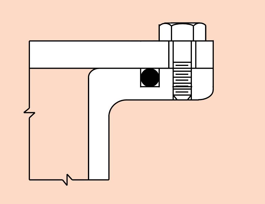
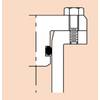
An o-ring in a groove with the endcap secured. (Courtesy Parker Seal Company)
It’s a mechanical problem first. If the seals don’t work, what’s inside doesn’t matter anymore.
Right off the bat: Parker Seal Company literally wrote the book on o-ring seals. There is no better design reference for o-ring seal design than the Parker O-ring Handbook (ORD-5700). A pdf is available for free at <www.parker.com>. It is mandatory reading for ocean engineers, and contains much more detail than possible in this article. Zoom in on the sections relevant to your work, then come back later and explore other seal designs, such as dovetail grooves, SAE Boss seals, crush seals, rotary seals, and others that might be helpful another day on another project. In my early years at Scripps, I found the Handbook a little confusing in parts. Older, experienced engineers and machinists helped me through it. In the long time since, from inside the Arctic Circle to the bottom of ocean trenches, Parker design guidelines never once let me down. Pretty epic win-loss ratio. In the early 1980’s, after a perplexing housing leak at sea, I reversed engineered and found underwater connectors from two companies that would predictably fail prematurely, at 1/3 of their catalog value, due to poor o-ring seal design. Presented with the evidence, the companies resisted change, so I presented at MTS conferences and wrote on “End-user Verification of Quality Control.” In the end, the companies revised their designs and obsoleted the poor ones.
Some basics:
1. The o-ring seal is a means for creating a barrier to fluid flow. The o-ring seal assembly consists of an o-ring installed in a groove. (Parker calls it a “gland,” but I’m an engineer and that makes be blush. So, it’s a “groove” and an “endcap.”)
2. Important: Assembly lubricants should always be used sparingly. They are just used to decrease friction and allow the o-ring to respond to pressure and move inside the groove.
3. The leading cause of o-ring failure in design is extrusion through a gap.
4. A Face seal is always better than a Radial seal because the gap the o-ring must seal is generally zero. (A radial seal on a plug in a bore requires some radial gap to just get the parts together. That’s a story for another day.) There is typically metal-to-metal engagement between the end cap and groove with a face seal, so there is no extrusion gap. Parker states, “Instances have been reported of sealing pressure of 200,000 psi with a 70-durometer o-ring.” I routinely test hadal depth components with face seals and 70-durometer o-rings to 18,500-psi using the Parker’s Design Chart A4-3 for o-ring face seals.
5. Think of o-ring elastomers as high viscosity incompressible fluids.
6. Larger o-ring cross-sections are more tolerant of surface imperfections, have better resistance to compression set, and have larger machining tolerances for the groove.
7. Smaller o-ring cross-sections require less space, and take less force to compress.
8. Soft durometers seal rougher surfaces.
9. Harder durometers resist extrusion better.
10. Selecting the proper o-ring elastomer requires some knowledge of fluid compatibility (ORD-5700, Section 7), operating temperature range, maximum pressure, time under pressure, and allowable compression force for assembly. For mid-latitudes in seawater, a good choice is 70 durometer Nitrile or Buna N (NBR). It’s inexpensive, has good shelf life, is fine with silicone grease, and readily available. EPDM is another good choice. Very low temperatures are tolerated by silicone, but you need a different lubricant than silicone grease.
11. There is a force multiplier to consider. Assuming the end cap is strong enough to resist ambient pressure at depth (See reference to “Under Pressure” below), the force acting on the endcap loads the smaller area of the face of the cylindrical pressure case below it. The land area supporting the multiplied force is further reduced by the size and placement of the face seal o-ring groove. Move the o-ring groove as close to the cylinder’s outer circumference as possible. If a back-up o-ring is desired, make it a radial seal.
Engineers can follow Parkers' short form for face seals, where general allowances are given (Parker ORD-5700, Design Chart A4-3), or refine the design for a specific application, including stretching an o-ring for a groove slightly larger than spec.
Design Approach
 Design sequence in layout is described above. Full design requires consideration of means to secure endcap and load o-ring. A partial vacuum may do the trick instead of a pattern of bolts. (Courtesy Parker Seal Company, adapted by author)
 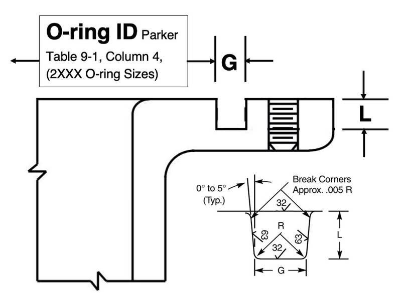 Determine o-ring groove size. Use O-ring ID (Parker Table 9-1, Column 4), G (groove width), and L (groove depth) from Parker Design Chart 4-3 (below). Groove detail is in the lower right. Courtesy Parker Seal Company)
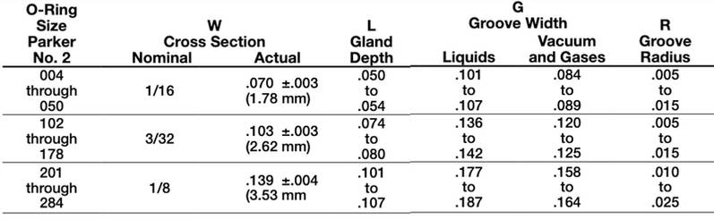 Design Chart 4-3: Design Chart for O-Ring Face Seal Grooves (Glands,) diameters 1/16”, 3/32”, and 1/8” only. (3/16”, 1/4”, 3/8”, and ½” not shown.) (Courtesy Parker Seal Company)
Other design notes:
1. Anodizing aluminum changes dimensions of the finished part. ODs get bigger by 0.002,” ID’s get smaller by 0.002,” groove depths remain the same, while change in some dimensions don’t matter. Adjust relevant part dimensions on the print. That’s the engineer’s job, not the machinist’s. Putting a note in 8-pt type in the lower left corner on the blue print that states “Dimensions apply after anodize” is asking for trouble. The machinist wants what you want: a perfect part the first time. Help him out. (A future article on anodizing aluminum is in the works.)
2. If the o-ring size you prefer is inbetween two standard sizes, Parker allows you to stretch the o-ring into a slightly larger groove, but not more than 5%. A stretched o-ring can result in a smaller cross-sectional area, requiring the depth of the groove to be made shallower to maintain recommended squeeze. (See Parker Handbook Sections 3.3 and 3.5).
Remember: You can stretch the o-ring fit a larger groove, but you cannot make the o-ring fit a smaller groove.
3. If needed, use of soft plastic probes or wood toothpicks to remove o-rings from grooves is recommended. Never use steel dental tools, paperclips, or other materials harder than the housing material.
4. Danger: dissimilar materials corrosion: An o-ring in a stainless-steel connector installed in an aluminum endcap could meet every Parker spec. But, two different metals in direct contact and submerged in seawater form a battery. The less noble material absolutely will corrode. Murphy’s Law guarantees the pitting corrosion will burrow under the o-ring. A second o-ring will delay the inevitable until the corrosion reaches the second sealing surface. Avoid dissimilar materials in direct contact.
5. Interesting note: An o-ring groove has two critical dimensions: the ID and the groove depth. The specified width of the groove already starts larger than the o-ring (Section 3.7), so the outer wall is not engaged in the sealing process for external pressure. The outer wall could even be eliminated, and the o-ring be exposed directly to the sea, though that also exposes the o-ring to some potential sources of damage. The outer wall acts like a shield to protect the o-ring from random damage.
6. Treat open o-ring seals with the same care as an open wound. Cleanliness and careful handling of the seals and sealing surfaces is crucial.
Additional notes:
- Parker’s Application Engineering Department personnel are available to review your project, including temperatures, pressures, groove (gland) design, bolt torque, surface finish, etc. They will offer alternate design ideas if that’s helpful. The Parker O-Ring & Engineered Seals Division is located in Lexington, KY, USA, Phone: 1-(859) 269-2351, Fax: 1-(859) 335-5128, www.parkerorings.com.
- Use of DeepSea’s, "Under Pressure", will assist the engineer in determining optimal pressure case and end cap dimensions. It’s very helpful for “what if” variations. The program may be downloaded for free at <https://www.deepsea.com/under-pressure-design-software/>.
- PREVCO Subsea Housings provides guidelines for handling and installation of o-rings. A properly designed o-ring seal can still fail if intent is not made to carefully clean, inspect, and install the o-ring. https://prevco.com/wp-content/uploads/2017/11/HANDLING-AND-INSTALLATION-OF-SEALS.pdf
- A pdf of the NRL Memorandum Report 4809, “O-Ring Installation for Underwater Components and Applications,” C. J. Sandwith, (1982), is available at the Global Ocean Design website https://www.globaloceandesign.com/other-useful-references.html
Acknowledgements
The author thanks Ray Haworth, Electric Boat, Frank Snodgrass, Mert Ingraham, Chuck Fleming, Baron Thomas, Scripps Institution, and Luigi Zoni, Parker Seal Company, for the design insights they have shared.
Citations:
Parker ORD-5700, 50th Anniversary Edition, <https://www.parker.com/content/dam/Parker-com/Literature/O-Ring-Division-Literature/ORD-5700.pdf>
“Lander Lab” is a hands-on column of Ocean Lander technologies and strategies, a unique class of unmanned undersea vehicles, and the people who make them. It is meant to serve the global ocean lander community in the manner of Make Magazine and other DIY communities.
Comments on this article, or suggestions for stories of interest to other Landereans are welcome. Ocean lander teams are encouraged to write in about their work. Please feel free to contact Kevin Hardy <[email protected]>.