Application Note: Pressure Relief Valves and Purge Ports
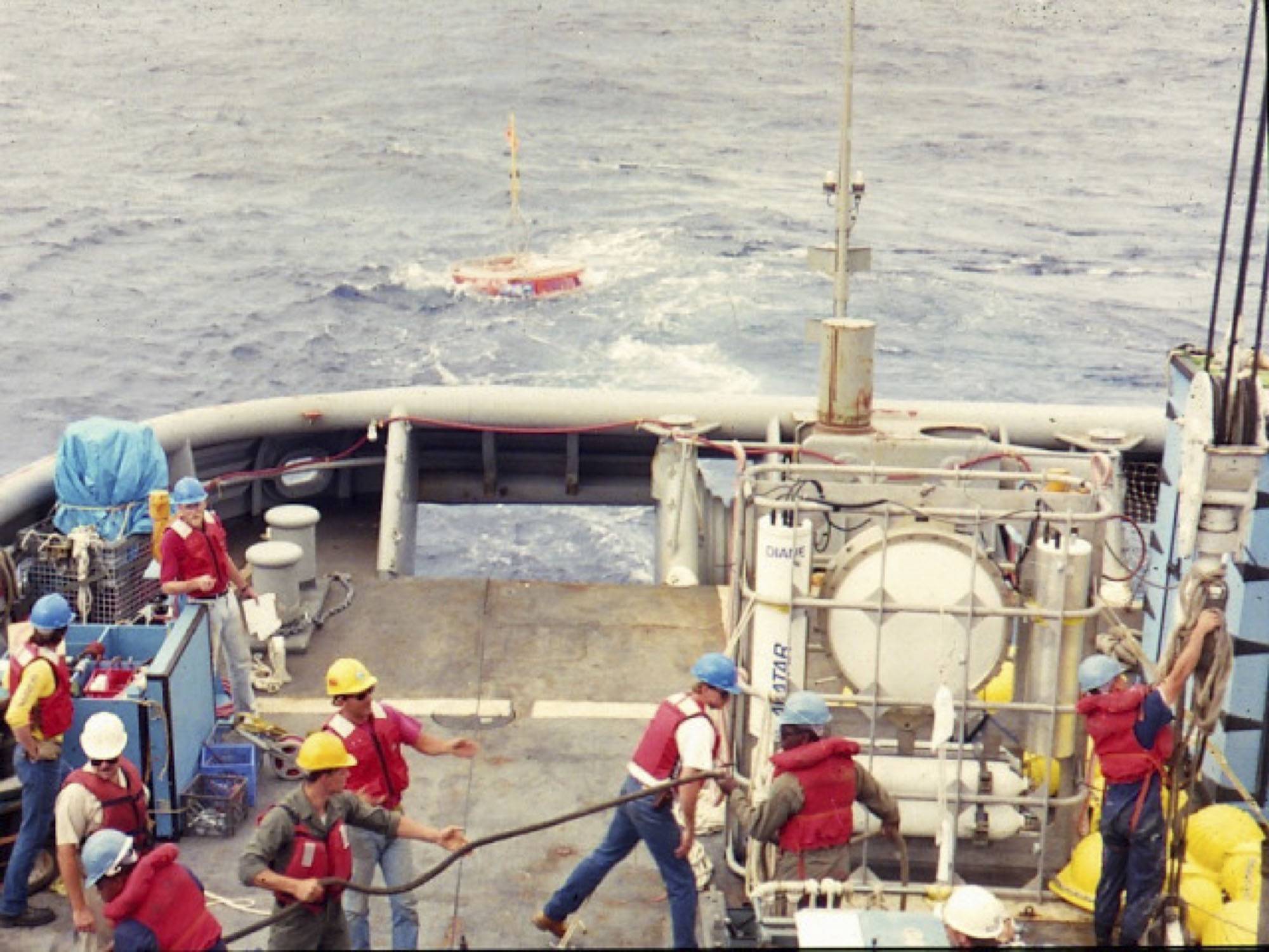
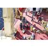
A pressure-compensated low-frequency source is deployed by Scripps Institution of Oceanography personnel off the USS Safeguard (ARS-50), circa 1986. Note the circular source in the standing equipment cage. It is pressure compensated by the four large compressed air flasks below it. Primary lithium cells and control electronics are in the vertical cylinders flanking the source to either side. The author is pictured on the far left. Lab mates Brian Dushaw, Steve Abbott, Doug Peckham, and Bob Trues
James Cameron’s second AVATAR movie introduced viewers to “The Way of Water.” It’s especially important for ocean engineers to “think like water.” Observe, study, and learn the way.
Fluid power refers to both liquid and gas. Two fluid power components to consider in controlling gas flow are the check valve, and the pressure relief valve. A check valve is an automatic one-way valve that constrains air flow to one direction. They can be useful in purge ports.
A pressure relief valve (PRV), sometimes called a pressure safety valve (PSV), or pop-off valve, is a safety device designed to protect a housing by venting high internal air pressure to the sea. The PRV automatically opens when pressure exceeds a predetermined differential limit, say 5psi over ambient, allowing pressure to vent in one direction. However, it can be shown that venting excess pressure and sealing out water are two different things.
Graphically, the different parts are represented by the symbols:
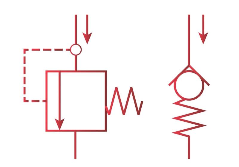 A PRV is represented graphically on the left. An adjustable PRV would show a diagonal arrow through the spring. A check valve is represented graphically on the right. Minimal spring force reduces the back pressure on the system. (Illustration courtesy of The Lee Company, Westbrook, CT.)
When a PRV opens in a topside shipboard environment, interior overpressure generally vents into an air-filled environment. Underwater, however, a PRV opens and vents directly into the ocean. It is literally like opening a door or window to the sea. It can be done, such as in a diver lock-out submersible (Figure 3), but it takes some thought before you do.
 Perry Oceanographics’ submersible Deep Diver, first introduced in 1973 as a diver lock-out sub, primarily operated in the North Sea oil fields. (illustration courtesy Perry Oceanographics, Riviera Beach, FL).
PRVs have a few simple parts, like a screen door closer. Push against the spring, the door opens. Release and the spring closes the screen door.

 Cross-section of a bronze, industrial spring-loaded open-discharge pressure relief valve. Parts, top-to-bottom: 8) Adjusting screw, 7) Locking Nut, 6) Spring disk, 5) Compression Spring, 4) Stem, 3) Sealing Disk, 2) Spring Chamber, and 1) Body (image courtesy: Newzel Industries, Mumbai, India).
For undersea application, PRVs have the added requirement to withstand substantial external pressure. Undersea PRV designs typically place the compression spring on the interior side lowering the PRV’s exterior profile and minimizing materials in contact with seawater. Size the PRV for maximum expected flow. As with any component that is part of a pressure housing, material selection (e.g., avoid dissimilar materials) and surface finish (e.g., passivation, hard anodize) requirements still apply. Marine PRV designs generally utilize the stem as the adjusting screw.
Two projects I worked on at Scripps incorporated pressure compensation systems for operation to a max depth of 1,500m (2,220 psi). We experienced some relevant mechanical behaviors.
The first was a buoyancy canister for a free-vehicle Mid-Ocean Float in the mid-1970’s. We jokingly called ourselves “the MOFia.” The free-vehicle tracked internal waves by measuring the vertical oscillations of an identified thermocline. A piston in a cylinder of a side-mounted pressure-compensated buoyancy canister provided variable displacement, which changed the density of the vehicle, which made the vehicle sink and rise, pulling a sting of fast-response thermistors behind it. After anchor drop, the vehicle was on it’s way back to the surface. The buoyancy canister vented internal pressure through a single PRV positioned at the bottom of the canister. The excess air always vented, and the unit always returned with a dry interior.
Some years later, the ATOC program used a moored low-frequency (150-Hz) source (Figure 1) made by HydroAcoustics (Rochester, New York) adapting an emerging environmental diagnostic technique known as Acoustic Thermometry to measure the volumetric average temperature of the ocean. The HLF-5 source utilized an open sump hydraulic system. The interior was pressure compensated to ambient pressure at operating depth using dry, compressed air. Two pressure relief valves, one a back-up for the other, vented internal air pressure as the system ascended to the surface at the end of the experiment. The PRVs were placed high to vent air, while the hydraulic oil was low and therefore not exhausted into the ocean. A graphite burst disk provided a third emergency pressure relief method which gratefully never ruptured. The two PRVs, positioned at the 10 and 2 o’clock positions, always worked.
Post-deployment, however, a saltwater trail was evident on the interior coming from the PRVs. Seawater in the open sump hydraulic oil confirmed a significant problem. Because the source was off at the time of recovery, no water was pumped through the hydraulic system.
With a little more study, we understood the inherent problem. Pressure relief valves have a “cracking pressure” and a “reseating pressure.” The opening and closing pressures are different due to hysteresis.
When open, a direct path from the interior to the exterior allowed excess internal air pressure to vent. Now think like water. Imagine a cup held upside-down in a pail of water. Air displaces water, water stays out. With the PRV placed on the bottom, interior air pressure that causes the PRV to open will prevent water from entering the housing, whether the seal is engaged or not. Placed anywhere else, a leak is likely, if not guaranteed, at the cracking and reseating pressures, exactly when forces are balanced. The PRV o-ring or gasket requires compression to seal, but right at the point where forces are balanced, just prior to or after the seal is engaged, water does what water does. It seeps in and flows downhill.
Our solution with the HLF-5 was to run a high-pressure hose from the air exhaust ports at the 10 and 2 positions to the bottom of the source where we placed the PRVs. Now the entry for the air to the PRV was at the high point well above the open sump oil on the interior, while the exhaust was at an exterior point below the lowest point of the interior, preventing water entry. Boom. Problem solved. No oil lost to the sea, no seawater inside.
Lesson 1: PRVs should be placed low.
There is a subtle problem with placing PRVs low: loose debris such as solder splatter, stripped wiring insulation, or lint falls with gravity and may land on the PRV interior side. If air is being directed over an open PRV seal, such as when the PRV vents, debris may land and stick on the sealing surface, compromising its ability to reseal. (See “Sealing Disk”, Figure 4). If there is a need to vent high interior pressure, that’s part of the deal. If the PRV is being used as a vacuum leak test/purge port it’s still part of the deal. Parker’s O-ring Handbook (ORD-5700) advises, “Cleanliness is vitally important to assure proper sealing action and long O-ring life. Every precaution must be taken to ensure that all component parts are clean at time of assembly. Foreign particles — dust, dirt, metal chips, grit, etc.— in the gland may cause leakage and can damage the O-ring, reducing its life.”
Sources of seal contamination on PRVs returned from deployment may also include biofouling, marine biogenic calcification, and salt build-up. Contact the PRV manufacturer for recommended post-deployment/pre-redeployment maintenance.
Here’s the catch: the interior PRV seal is impossible to inspect directly. A leaky PRV seal could be found if a vacuum leak test were performed from a separate purge port. End-users are otherwise left to hope, luck, chance, and wishful thinking. “It’s probably OK” are not words to speak when facing King Neptune. Davy Jones keeps what he covets. You need to know for sure. An internal pressure sensor connected to an external read-out is another solid means to confirm seal integrity.
Suggestions from motivated sales personnel that a PRV can perform a dual use play into this problem. One PRV manufacturer offers an interior filter to help reduce the potential of debris falling into the PRV, which is helpful. An end-user could improve their odds by rotating the housing on the bench so the PRV is high while performing the purge function using the PRV.
This brings us to the second caveat to the dual use approach. With some marine PRVs, attaching the purge port adapter can inadvertently change the pop-off setting. This is because the center stem of the PRV may also be used as the adjustment screw to set the cracking pressure. Some manufacturer’s instructions carry a clear warning to end-users to be careful, such as, “Install the vacuum/fill accessory by pushing it down over the body of the relief valve. … Once aligned, push down lightly on the plunger puller and turn it approximately 4 times clockwise <to> engage the threads in the … PRVs plunger. DO NOT continue turning until tight, as this will result in altering the set point of your … PRV.” This company also provides instructions on how to reset the cracking pressure. Add that to your pre-deployment checklist.
This second problem may be limited as the adjustable cracking pressure range is 5-15 psi, more or less. But confirm with the PRV manufacturer so that you know for certain.
Lesson 2. Only use PRVs for their intended purpose: venting internal overpressure.
Which brings us to purge ports. There are two kinds of purge ports: open and self-sealing. The open purge port has a small orifice behind a sealing plug or screw. The small orifice controls the rate of flow through a small diameter center hole while the final seal screw or sealing plug is installed. The intention is to be quick about it so not too much vacuum is lost by moist marine air re-entering the housing. Air being drawn into the housing may also carry debris across a greased o-ring sealing surface where it may compromise the final o-ring seal. (See Lander Lab #7, “Managing Moisture in SubSea Housings”, MTR, March/April 2023.)
A self-sealing purge port, such as made by Global Ocean Design (San Diego, CA), incorporates an interior check valve. When the purge system adapter is connected, the check valve is held open and a free flow of air is allowed in two-directions. When the purge system adapter is removed from the self-sealing purge port, a spring-loaded check valve closes, and air flow is cut-off.
A vacuum leak test using the Global Ocean Design Deck Purge Box (Figure 5) can check all seals, including those of a PRV, minus the last one, the pressure proof cap. The final seal, a face seal, can be cleaned, inspected and carefully installed with no rush. There’s a very high probability of getting it right if done with care and a close eye.
Purge Systems provide the means to pull a partial vacuum on an undersea housing, remove entrained moisture, vacuum test all the housing seals, and preload the housing o-rings before deployment.
A purge system removes moist entrained air, replacing it with dry air. A focus on backfilling with dry nitrogen is misplaced. It’s not oxygen that needs to be removed, it’s water vapor. It’s the dew point at cold ocean depth we’re worried about. Dry air could also come from a SCUBA tank, or CO2 soda maker flask.
If an end-user’s housing is constrained to using a PRV as a purge port, the manufacturer’s PRV’s adapter can easily attach to the Deck Purge Box.
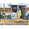
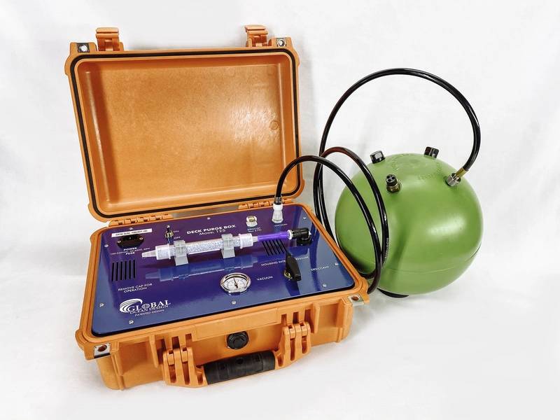 A Deck Purge Box from Global Ocean Design is an integrated unit without hazmat that performs the vacuum leak test and desiccation process of a housing’s entrained air. It is simple to secure to a benchtop of a rolling ship. (Photo courtesy of Global Ocean Design LLC)
Another danger to avoid: Use of a high-pressure bottle to force air in carries an obvious danger of blowing off an endcap when the PRV is being used as a purge port. Global Ocean Design’s Deck Purge Box removes this hazard by utilizing the interior vacuum already made by the vacuum pump to draw air in. Moist marine air is directed over a desiccant cartridge, which removes suspended moisture on contact. It is self-limiting. When interior and exterior pressures are equal, air flow stops. This approach also eliminates the problems of shipping high pressure bottles, then refilling them in a foreign port. If high pressure bottles are emptied at sea, that’s it, no more purging. But if the indicating desiccant is saturated, spares can be swapped in, or a used one can be recharged in the ship’s galley’s oven in a couple of hours.
Multiple purge cycles to ½ bar remove half the remaining water vapor each time. One cycle takes out 50%. The second cycle takes out another 25% of the original water vapor. A third cycle takes out 12.5% of the original water vapor. Three cycles together remove 87.5% of the original water vapor. So look for a system that can provide multiple purge cycles conveniently.
Sea-going teams also know that loose items need to be tied down before leaving the dock. Global Ocean Design’s Deck Purge Box is a single integrated unit, easily secured to a bench top. It incorporates a universal power supply, so it readily adapts to foreign ships-of-opportunity. There are no hazmat components such as high-pressure bottles or biohazardous chemicals. It is CE compliant. It has been in production for over 15 years, and used on housings deployed at all latitudes and all depths, for short and long durations, by worldwide research institutions and industries.
PRVs are a useful device when the potential for high interior pressure needs to be mitigated. PRVs should be used for their primary intended purpose: venting excess interior pressure. The companies that make them do so with the best interest of the end-user in mind. There are important subtleties to understand for their successful incorporation into subsea equipment. Use a dedicated purge port when one is called for.
“Lander Lab” is a hands-on column of Ocean Lander technologies and strategies, a unique class of unmanned undersea vehicles, and the people who make them. It is meant to serve the global ocean lander community in the manner of Make Magazine and other DIY communities.
Comments on this article, or suggestions for stories of interest to other Landereans are welcome. Ocean lander teams are encouraged to write in about their work. Please feel free to contact Kevin Hardy <[email protected]>.